
Pavement joint cutting machine

A seam cutting machine and steel bar cutting machine technology, which is applied in the field of construction machinery, can solve the problems of wasting water resources and uneven cooling water for cutting blades, and achieve good effects, good water storage effects, and water saving effects

Pending Publication Date: 2018-09-18
长葛市老城昌宝建筑机械配件厂
View PDF0 Cites 2 Cited by
  • Summary
  • Abstract
  • Description
  • Claims
  • Application Information

AI Technical Summary

Problems solved by technology

[0002] The road seam cutting machine has a frame on which a power shaft is installed. The power shaft has a cutting blade seat for installing a cutting blade. The cutting blade has a ring-shaped structure. Backing plate, circular second backing plate and tightening nut, when in use, the cutting piece is just installed between the first backing plate and the second backing plate and fixed with the tightening nut; in order to make the cutting piece cool down in time , a water spraying device is also installed on the frame, and the water spraying device has a cooling water outlet pipe, and the cooling water can be poured on the cutting piece to make the cutting piece cool down in time; in the prior art, there is no structure to help watering on the first backing plate , the cooling water is directly poured onto the cutting piece, which has the disadvantages of wasting water source and uneven cooling water of the cutting piece

Method used


Image

  • Pavement joint cutting machine
  • Pavement joint cutting machine
  • Pavement joint cutting machine

Examples


Embodiment Construction

[0019] The present invention will be further described below in conjunction with the drawings.

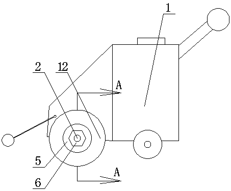
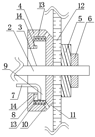
[0020] Such as figure 1 , 2 , 3, a road cutting machine includes a frame 1, a power shaft 2 is installed on the frame, the power shaft has a cutting blade seat 3 on which a cutting blade is installed, and the cutting blade seat has a circular ring The first backing plate 4, the ring-shaped second backing plate 5 and the tightening nut 6;

[0021] A water spraying device is also installed on the rack, and the water spraying device has a cooling water outlet pipe 7;

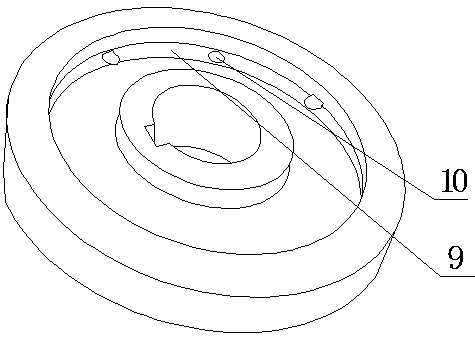
[0022] It is characterized in that: there is a groove 8 around the outer side of the first backing plate, and the groove is formed by the outer edge of the first backing plate being extended outwards and then folded inward, and the first backing plate is folded inward to form a torus. The opening 9 of the groove faces its central axis, and there are a plurality of evenly distributed small holes 10 on the bottom plate of the g...


PUM


Abstract

The invention relates to the technical field of building machinery and provides a pavement joint cutting machine. The pavement joint cutting machine comprises a frame; a power shaft is mounted on theframe; a cutting blade seat for mounting a cutting blade is arranged on the power shaft; a circular ring-shaped first backing plate, a circular ring-shaped second backing plate and a tightening nut are arranged on the cutting blade seat; a water-spraying device is also mounted on the frame; a water outlet pipe for cooling water is arranged on the water-spraying device; a groove is formed around the external side of the first backing plate; the groove is formed in such a way that the edge of the external side of the first backing plate is folded inside after extending outside; the opening of the groove faces towards the position of the central axis of the groove; a plurality of uniformly distributed small holes are also formed in a bottom plate of the groove; the small holes run through thebottom plate of the groove; outlets of the small holes are inclined to the right side; and a water outlet of the water outlet pipe is arranged towards the groove. Therefore, the pavement joint cutting machine has the advantages that water sources are saved and the cooling water pouring effect is good.

Description

Technical field [0001] The invention relates to the technical field of construction machinery, in particular to a pavement slitting machine. Background technique [0002] The pavement slitting machine has a frame on which a power shaft is installed. The power shaft has a cutting blade seat on which the cutting blade is installed. The cutting blade has a circular structure. The cutting blade seat has a circular first The backing plate, the circular second backing plate and the tightening nut. When used, the cutting piece is installed between the first backing plate and the second backing board and fixed with the tightening nut; in order to cool the cutting piece in time , The water spray device is also installed on the frame, the water spray device has a cooling water outlet pipe, and the cooling water can be poured on the cutting blade to cool the cutting blade in time; in the prior art, the first pad has no structure to help watering , Cooling water is poured directly onto the ...

Claims


Application Information

Patent Timeline
Patent Type & Authority Applications(China)
IPC IPC(8): E01C23/09
CPCE01C23/0933
Inventor 耿彦昌
Owner 长葛市老城昌宝建筑机械配件厂
Learn More