Relay reed flange structure

A flanging structure and relay technology, applied in the direction of relays, electromagnetic relays, electromagnetic relay details, etc., can solve the problems of plastic shavings and achieve the effect of reducing the generation of plastic shavings

Inactive Publication Date: 2018-09-18
HUANGSHAN WANGRONG ELECTRONICS
View PDF6 Cites 0 Cited by
  • Summary
  • Abstract
  • Description
  • Claims
  • Application Information

AI Technical Summary

Problems solved by technology

Users urgently need to solve the problem of plastic chips generated during the operation of relays

Method used


Image

  • Relay reed flange structure
  • Relay reed flange structure
  • Relay reed flange structure

Examples


Embodiment Construction

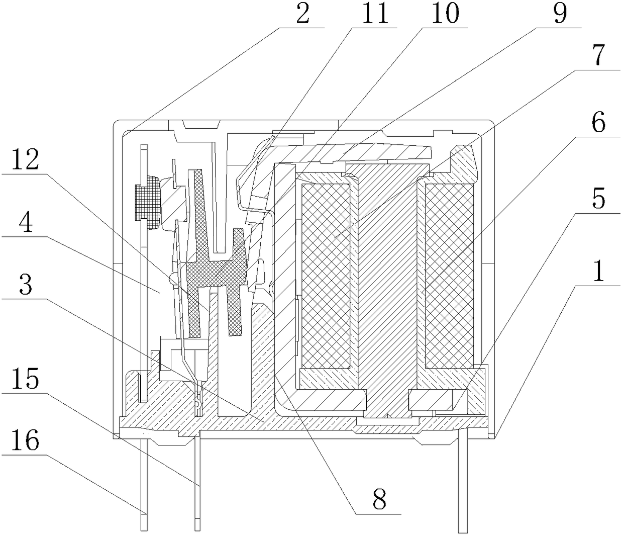
[0015] A relay reed flanging structure, which includes a base, the base is provided with a casing, the base is provided with a partition, and the partition forms a coil cavity and a terminal cavity in the casing. , the coil chamber is provided with a skeleton, the skeleton is provided with a coil, and the coil chamber is provided with an iron frame to fix the coil, the coil is provided with an armature, and one end of the armature is provided with a push piece , the terminal cavity is provided with a reed, and the push piece is in contact with the reed.

[0016] Preferably, the armature is L-shaped, one end of the armature is installed in the coil cavity, and the other end of the armature is installed on the push piece, and the armature is fixedly connected to the coil cavity by a hook.

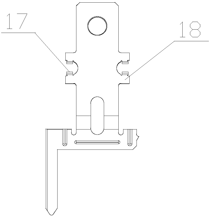
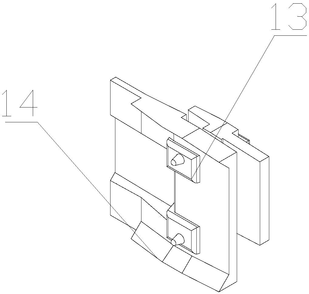
[0017] Preferably, a support plate is provided in the terminal cavity, the push piece is I-shaped, a boss is provided on the push piece, arc-shaped edges are provided at both ends of the push...


PUM


Abstract

The invention discloses a relay reed flange structure which comprises a base. The base is provided with a housing and a separator plate. The separator plates divides the inner part of the housing intoa coil chamber and a terminal chamber. The coil chamber is internally provided with a frame. The frame is provided with a coil. The coil chamber is internally provided with an iron frame for fixing the coil. The coil is provided with an armature. One end of the armature is provided with a push plate. The terminal chamber is internally provided with a reed. The push plate is in contact connectionwith the reed. Compared with prior art, the upper flange of a C reed is provided with the arc-shaped crimped edge so that a pushing boss dodges the sharp part of the stroke hole edge in the reed, thereby effectively preventing generation of plastic shreds. Furthermore through changing the pushing part of the pushing boss from a cylinder to a cone, the pushing part matches the flange part of the reed more effectively, thereby reducing generation of plastic shreds.

Description

technical field [0001] The invention relates to the field of relay metal processing, in particular to a relay reed flanging structure. Background technique [0002] As a confidential component, relays are mostly caused by foreign matter in use. Preventing foreign matter is a headache for major relay manufacturers. Users urgently need to solve the problem of plastic chips generated during the operation of the relay. Contents of the invention [0003] In order to overcome the defects of the prior art, the present invention provides a relay reed flanging structure. [0004] The present invention adopts the following technical solutions: a relay reed flanging structure, which includes a base, a housing is provided on the base, a partition is provided on the base, and the partition connects the housing A coil cavity and a terminal cavity are formed inside, the coil cavity is provided with a skeleton, the skeleton is provided with a coil, and the coil cavity is provided with a...

Claims


Application Information

Patent Timeline
Patent Type & Authority Applications(China)
IPC IPC(8): H01H50/04H01H50/64
CPCH01H50/64H01H50/041
Inventor 不公告发明人
Owner HUANGSHAN WANGRONG ELECTRONICS
Why Eureka
Try Eureka