Array radio frequency optical fiber link phase monitoring method, system and phase adjustment method

A radio frequency fiber and link technology, applied in the field of array radio frequency signal transmission, can solve the problems of unreported, signal power attenuation, large amplitude fluctuation, etc., to meet the requirements of stable phase and maintain stable phase.

Active Publication Date: 2021-02-26
SOUTHWEST CHINA RES INST OF ELECTRONICS EQUIP
View PDF3 Cites 0 Cited by
  • Summary
  • Abstract
  • Description
  • Claims
  • Application Information

AI Technical Summary

Problems solved by technology

[0003] At present, the transmission of radio frequency signals generally adopts cables. The main problems of using cables to transmit signals are as follows: 1) The signal loss is large, and the signal power attenuation is serious when the distance is long; 2) The amplitude fluctuates greatly with frequency, and in a wide frequency range, Great impact on system performance; 3) Poor electromagnetic compatibility, prone to mutual interference in places with dense wiring such as aircraft; 4) Large in size, heavy in weight, difficult in layout, and inflexible in bending, which brings a lot of problems to the application on aircraft question
This document points out the application direction of radio frequency optical fiber links, but there is no specific implementation method description
The document "Demonstration of amicrowave photonic link insertion into the ALR-2001 EW system" (T. S. Priest, M. E. Manka, K.K. Gupta. IEEE Conference on Optical Fiber Technology. 2006:31-33) discusses the application of radio frequency optical fiber link technology in airborne Electronic warfare system, obtained some preliminary results, but did not mention the implementation and performance of fiber optic links for the application of array radio frequency signals
[0006] At present, the radio frequency optical fiber link technology has received extensive attention, but the research focus is mainly on the single-channel point-to-point method, and there is no report on the implementation method of the array application on the aircraft platform

Method used


Image

  • Array radio frequency optical fiber link phase monitoring method, system and phase adjustment method
  • Array radio frequency optical fiber link phase monitoring method, system and phase adjustment method
  • Array radio frequency optical fiber link phase monitoring method, system and phase adjustment method

Examples


Embodiment Construction

[0033] In order to make the object, technical solution and advantages of the present invention clearer, the present invention will be further described in detail below in conjunction with the accompanying drawings and embodiments. It should be understood that the specific embodiments described here are only used to explain the present invention, not to limit the present invention.

[0034] Any feature disclosed in this specification (including the abstract and drawings), unless specifically stated, can be replaced by other equivalent or similar purpose alternative features. That is, unless expressly stated otherwise, each feature is one example only of a series of equivalent or similar features.

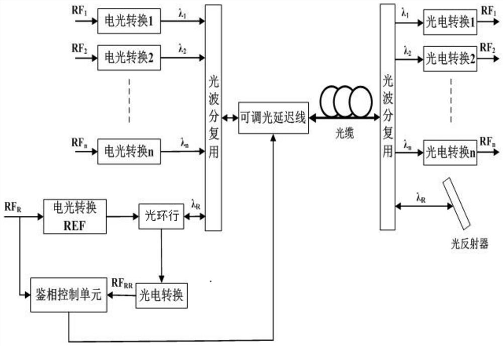
[0035] For the array radio frequency optical fiber link, due to the long transmission distance, the phase of the signal will constantly change with the external conditions.

[0036] Such as figure 1 As shown, the present invention provides a method for monitoring the phase change o...


PUM


Abstract

The invention provides a phase change monitoring method and monitoring system of an array radio frequency optical fiber link signal, and a signal phase adjusting method. The phase change monitoring method comprises the steps of: setting a path of reference radio frequency signal FRR; resolving and restoring an optical signal after the reference radio frequency signal passes through an array radiofrequency optical fiber link and arrives at a receiving terminal; reflecting and returning the resolved and restored optical signal according to the original path; acquiring a signal RFRR with same reference frequency at a transmitting terminal through a photovoltaic conversion; according to a phase delay relationship between the reference radio frequency signal FRR and the signal RFRR with same reference frequency, acquiring the phase change of the array radio frequency optical fiber link; and, according to a phase difference of compared two paths of signals, acquiring a corresponding error voltage, generating a control voltage and adjusting the delay time of an adjustable optical fiber delay line. Compared with the prior technology, the method is suitable for stabilizing the phase of thebroadband radio frequency signal, adjusting the signal delay on a public path, and simultaneously satisfies the requirement of stabilizing the phase of the radio frequency signal of each path.

Description

technical field [0001] The invention relates to an array radio frequency optical fiber link signal phase change monitoring method, a monitoring system and a signal phase adjustment method, and relates to the field of array radio frequency signal transmission in electronic equipment such as electronic warfare and radar. Background technique [0002] Electronic equipment such as electronic warfare and radar must realize corresponding functions by receiving and processing signals from the outside world. In order to achieve higher performance of the system, the radio frequency signal received and transmitted by the antenna unit adopts an array method. On occasions such as aircraft, ships, and the ground, there is often a certain distance between the array antenna unit and the processing unit, and it is necessary to transmit the broadband array radio frequency signal to the corresponding central processing unit. [0003] At present, the transmission of radio frequency signals ge...

Claims


Application Information

Patent Timeline
Patent Type & Authority Patents(China)
IPC IPC(8): H04B10/079
CPCH04B10/0795
Inventor 陈吉欣鄢勃贾朝文刘翔师勇班晓东李燕平雷佳科张丰张学帅刘泊
Owner SOUTHWEST CHINA RES INST OF ELECTRONICS EQUIP
Why Eureka
Try Eureka