Distortion compensation circuit

A distortion compensation and circuit technology, applied in the direction of look-up table adaptive pre-distortion, improving amplifiers to reduce nonlinear distortion, electrical components, etc., can solve problems such as bit error rate degradation, BER degradation of phase modulated signals, adjacent channel interference, etc.

Inactive Publication Date: 2009-04-15
AI电子株式会社
View PDF0 Cites 0 Cited by
  • Summary
  • Abstract
  • Description
  • Claims
  • Application Information

AI Technical Summary

Problems solved by technology

[0002] In a high-frequency power amplifier circuit, the operating point is usually set near the saturation point where the additional efficiency is high, so a lot of nonlinear distortion occurs
Due to such nonlinear distortion, 3rd, 5th, etc. inter-modulation occurs, and due to such inter-modulation, the degradation of the C / N ratio (Carrier to Noise ratio) in the frequency band occurs, resulting in BER (Bit ErrorRate , bit error rate) degrades such problems
In addition, the band-limited input signal spreads out of the band due to 3rd and 5th cross-modulation, causing the problem of causing interference to adjacent channels.
In addition, there is a problem that the BER of the phase modulated signal deteriorates due to phase noise caused by AM-PM conversion

Method used


Image

  • Distortion compensation circuit
  • Distortion compensation circuit
  • Distortion compensation circuit

Examples


no. 1 Embodiment approach

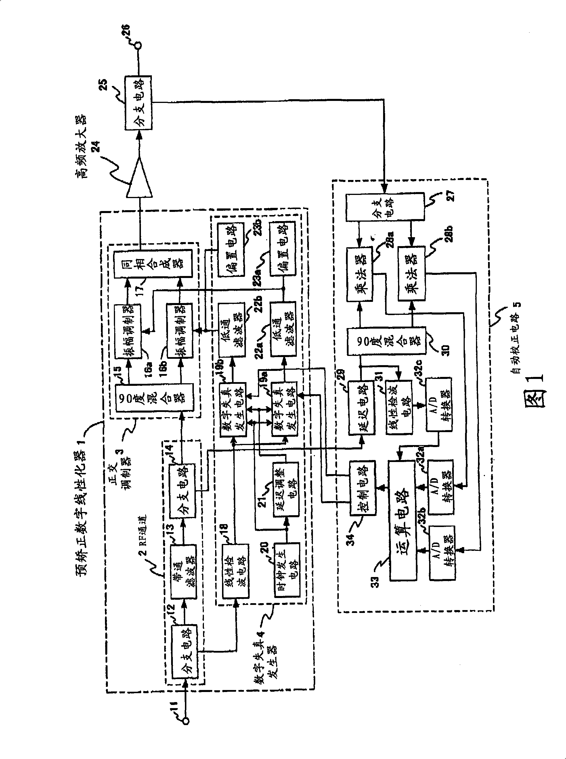
[0123] Hereinafter, embodiments of the present invention will be described with reference to the drawings. FIG. 1 is a diagram showing the configuration of a predistortion digital linearizer 1 according to a first embodiment of the present invention.

[0124] In FIG. 1 , the RF channel 2 is composed of a branch circuit 12 , a bandpass filter 13 and a branch circuit 14 . The input signal from the input terminal 11 is branched into signals of two paths by the branch circuit 12 . The main signal branched by branch circuit 12 is supplied to branch circuit 14 via bandpass filter 13 . The bandpass filter 13 secures the frequency band of the input signal. This input signal is branched into signals of two paths by the branch circuit 14 .

[0125] The quadrature modulator 3 is composed of a 90-degree mixer 15 , amplitude modulators 16 a , 16 b , and an in-phase combiner 17 . The amplitude modulators 16a, 16b are multipliers. The in-phase combiner 17 is an adder. The main signal b...

no. 2 Embodiment approach

[0470] FIG. 32 is a diagram showing the configuration of the predistortion digital linearizer 101 according to the second embodiment of the present invention. In the above-mentioned first embodiment, the input signal is divided into the in-phase signal component and the quadrature signal component, and the pre-distortion process is performed. In contrast to this, in the present embodiment, the pre-distortion is performed by dividing the signal into the amplitude component and the phase component. deal with.

[0471] In FIG. 32 , the RF channel 102 is composed of a branch circuit 112 , a bandpass filter 113 , and a branch circuit 114 . The input signal from the input terminal 111 is branched into signals of two paths by the branch circuit 112 . The main signal branched by branch circuit 112 is supplied to branch circuit 114 via bandpass filter 113 . The input signal is branched into signals of two paths by the branch circuit 114 .

[0472] The phase and amplitude adjuster 10...


PUM


Abstract

To provide a distortion compensation circuit capable of performing highly-accurate nonlinear distortion compensation even for an ultra-high frequency and a wide band. [MEANS FOR SOLVING PROBLEMS] A distortion generation circuit for generating distortion component data for compensating nonlinear distortion of a high-frequency amplifier includes a memory matrix (51), a level comparator (52), and a D/A converter (53). The memory matrix (51) stores distortion component data expressed by an even-number degree multinomial corresponding to an envelope level value for each row in the horizontal direction. The level comparator (52) compares the envelope level to a plurality of reference voltages and generates a row selection signal for selecting one of the rows in the memory matrix (51) according to the comparison result. The D/A converter (53) converts the distortion component data expressed by the even-number degree multinomial which has been read out, into an analog signal. This enables output of a waveform of the distortion component almost in real time, thereby performing a highly-accurate nonlinear distortion compensation even for an ultra-high frequency and a wide band.

Description

technical field [0001] The present invention relates to a distortion compensating circuit suitable for compensating nonlinear distortion generated by a high frequency power amplifier. Background technique [0002] In a high-frequency power amplifier circuit, usually, the operating point is set near the saturation point where the additional efficiency is high, so a lot of nonlinear distortion occurs. Due to such nonlinear distortion, 3rd, 5th, etc. inter-modulation occurs, and due to such inter-modulation, the degradation of the C / N ratio (Carrier to Noise ratio) in the frequency band occurs, resulting in BER (Bit ErrorRate , bit error rate) degradation of such problems. In addition, the band-limited input signal is spread out of the band by 3rd and 5th interleaving modulation, causing a problem of causing interference to adjacent channels. In addition, there is a problem that the BER of the phase modulation signal deteriorates due to phase noise caused by AM-PM conversion....

Claims


Application Information

Patent Timeline
Patent Type & Authority Applications(China)
IPC IPC(8): H03F1/32
CPCH03F2201/3233H03F1/3247H03F1/32H03F3/189
Inventor 小川宏
Owner AI电子株式会社
Why Eureka
Try Eureka