Cable winding device

A winding device and cable technology, which is applied in transportation and packaging, conveying filamentous materials, thin material processing, etc., can solve the problems such as the winding device cannot work when the winding device is shut down, the production efficiency is reduced, and the continuous production capacity is poor.

Inactive Publication Date: 2018-09-21
德阳市德东电工机械制造有限公司
View PDF0 Cites 4 Cited by
  • Summary
  • Abstract
  • Description
  • Claims
  • Application Information

AI Technical Summary

Problems solved by technology

[0004] The object of the present invention is: in order to solve the problem that the existing cable winding device cannot work when the winding reel is loaded and unloaded, resulting in poor continuous production capacity and reduced production efficiency, the present invention provides a cable winding device

Method used


Image

  • Cable winding device

Examples


Embodiment 1

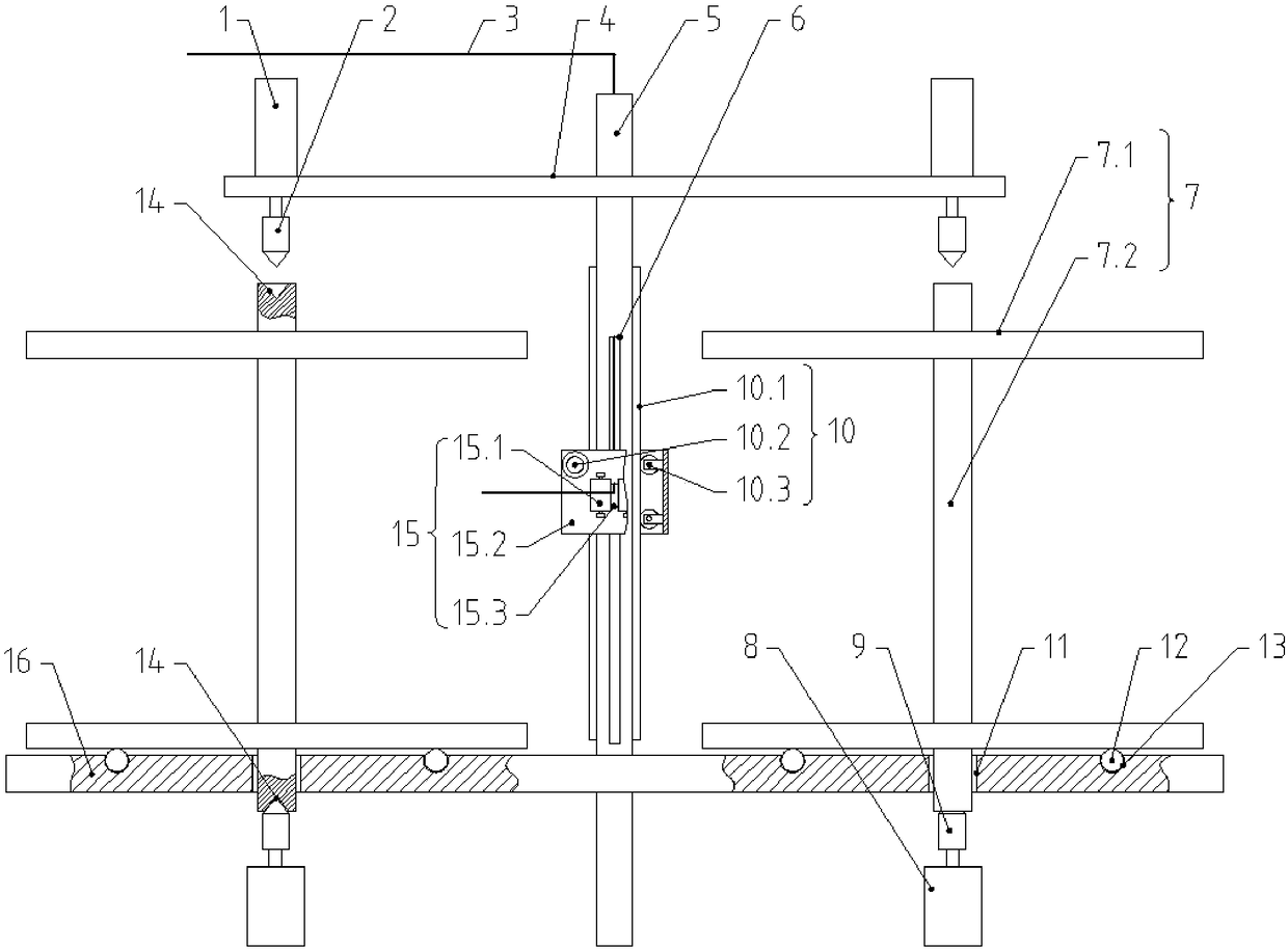
[0018] A cable 3 winding device, including a bracket and a winding reel 7 arranged on the bracket, the winding reel 7 includes a support rod 7.1 and baffles 7.2 sleeved at both ends of the support rod 7.1, and the bracket includes a vertically arranged hollow pillar 5. A horizontal support plate 16 is provided on the outer wall of the bottom of the hollow pillar 5. On the support plate 16, winding discs 7 are provided on both sides of the hollow pillar 5. The support plate 16 is provided with a through hole that can accommodate the end of the support rod 7.1 11. A drive mechanism that can contact and cooperate with the end of the support rod 7.1 is provided under the support plate 16. A cable 3 is provided inside the hollow support 5. An opening 6 for the cable 3 to pass through is vertically opened on the hollow support 5. On the hollow support 5 A wire mechanism 15 that can move up and down is sleeved.

[0019] The cable 3 enters the inside of the hollow pillar 5 from the to...

Embodiment 2

[0022] This embodiment improves on the basis of Embodiment 1:

[0023] The drive mechanism includes a drive motor 8, the output end of the drive motor 8 is provided with a connection block a9 that can be in contact with the end surface of the support rod 7.1, the end of the connection block a9 is tapered, and the end surface of the support rod 7.1 is provided with a cone that cooperates with the connection block a9 Shaped groove 14.

Embodiment 3

[0025] This embodiment improves on the basis of Embodiment 1:

[0026] The wire mechanism 15 includes a sleeve 15.2 sleeved on the hollow pillar 5, the sleeve 15.2 is provided with a wire port 15.3 corresponding to the opening 6, and the outer wall of the sleeve 15.2 is provided with guide wheels 15.1 on both sides of the wire port 15.3. The cylinder 15.2 cooperates with the hollow pillar 5 through the lifting mechanism 10.


PUM


Abstract

The invention discloses a cable winding device, and relates to the technical field of cable processing equipment. The problems that when an existing cable winding device winder is assembled and disassembled, a winding device stops and cannot work, so that the continuous production capacity is poor, and the production efficiency is lowered are solved. The device comprises a support and winders arranged on the support, each winder comprises a support rod and baffles sleeving the two ends of the support rod, the support comprises a vertically arranged hollow supporting column, a horizontal supporting plate is arranged on the outer wall of the bottom of the hollow supporting column, the winders are arranged on the portions, on the two sides of the hollow supporting column, of the supporting plate, a through hole which can contain the tail end of the support rod is formed in the support plate, a driving mechanism which can be in contact cooperation with the tail end of the support rod is arranged on the lower portion of the supporting plate, a cable is arranged in the hollow supporting column, an opening allowing the cable to go through is vertically formed in the hollow supporting column, and a cable leading mechanism capable of moving vertically sleeves the hollow supporting column.

Description

technical field [0001] The invention relates to the technical field of cable processing equipment, and more specifically relates to a cable winding device. Background technique [0002] In the 1860s, mankind started the Industrial Revolution and created huge productivity. With the invention and application of the steam engine, mankind entered the "Steam Age". Electric Age" and continues to this day. As one of the most important energy sources in the "Electrical Age", electric energy is transmitted by cables, which are widely used in industry and daily life. Cables are usually made of conductor wires that are treated and then wrapped with an insulating layer. For the convenience of transportation and sales, cables usually need to be wound into coils after production. [0003] In the current production process, the cable winding is realized by the winding device. The existing winding device usually uses the device to tighten the two ends of the winding reel, and then drives ...

Claims


Application Information

Patent Timeline
IPC IPC(8): B65H54/54B65H67/04
CPCB65H54/54B65H67/0411B65H67/0417B65H2701/34
Inventor 张大海
Owner 德阳市德东电工机械制造有限公司
Why Eureka
Try Eureka