Steel reinforcement connecting device

A connecting device and steel bar technology, which is applied in the direction of structural elements, building components, building reinforcements, etc., can solve problems such as the inability to realize the overall connection of steel bar parts, the difficulty of ensuring the quality of steel bar connections, and the inability to realize steel bar connections, etc., to ensure the quality of building structures , fast construction speed and simplified construction process

Inactive Publication Date: 2018-09-21
宁波市圣钢科技发展有限公司
View PDF6 Cites 4 Cited by
  • Summary
  • Abstract
  • Description
  • Claims
  • Application Information

AI Technical Summary

Problems solved by technology

In the connection construction of this kind of steel bar parts, the steel bar can only move in the axial direction and cannot rotate
Therefore, the overall connection of steel bar parts cannot be realized by using the existing steel bar connection method
For example, prefabricated building technology is being vigorously promoted now. Since the exposed steel bars of the components cannot be rotated, the existing mechanical connection technology of steel bars cannot realize the connection of steel bars. The steel bar connections between components in prefabricated buildings can only be connected with grouting sleeves. However, the cost of grouting sleeve is high, the construction process is cumbersome and complicated, the quality of grouting construction directly affects the quality of the project, and the quality of steel bar connection is difficult to guarantee

Method used


Image

  • Steel reinforcement connecting device
  • Steel reinforcement connecting device
  • Steel reinforcement connecting device

Examples


Embodiment Construction

[0028] The present invention will be further described below in conjunction with drawings and embodiments.

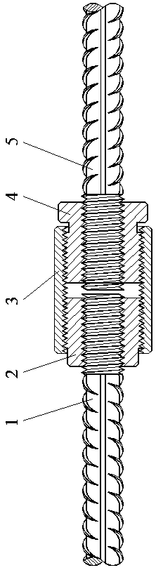
[0029] see Figure 1 to Figure 6 , the casing self-locking steel bar connection device according to the embodiment of the present invention, which includes the connected steel bars 1, 5, through the self-locking sleeve 2, the positioning self-locking sleeve 4 and the sleeve 3.

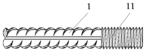
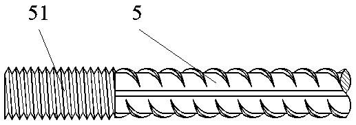
[0030] One of the two connected steel bars is a steel bar 1 with a short external thread 11 at the end, and the other is a steel bar 5 with a long external thread 51 at the end.

[0031] The material of the self-locking sleeve 2 is high-quality carbon steel, and the self-locking sleeve is provided with an internal thread 22 that matches the external thread 11 on the connected steel bar 1. The screwing of the internal and external threads will pass through the self-locking The sleeve 2 is installed on the steel bar 1 to be connected, and the self-locking sleeve 2 is also provided with an externa...


PUM


Abstract

The invention provides a steel reinforcement connecting device which comprises a connected steel reinforcement, a passing self-locking sleeve, a positioning self-locking sleeve and a sleeve. The connected steel reinforcement is provided with a thread at one end. An inner hole of the passing self-locking sleeve is penetrating and is provided with an inner thread in threaded fit with the connected steel reinforcement. A section of outer thread of the passing self-locking sleeve is formed on the outer surface at one end of the passing self-locking sleeve. An inner hole of the positioning self-locking sleeve is penetrating and is provided with an inner thread in threaded fit with the steel reinforcement. A section of outer thread of the positioning self-locking sleeve is formed in the outer surface at one end of the positioning self-locking sleeve. The two ends of the sleeve are opened. Inner threads in threaded fit with the outer thread of the passing self-locking sleeve and the outer thread of the positioning self-locking sleeve are separately arranged in opened inner hole in two ends.

Description

technical field [0001] The invention relates to a method and a device for connecting steel bars in building structures. The device is suitable for vertical, horizontal and oblique connections of steel bars in cast-in-place construction and prefabricated buildings. Background technique [0002] The mechanical connection forms of steel bars in existing building structures mainly include: cold extrusion connection and screw connection. [0003] The cold extrusion connection adopts a steel casing with high ductility and moderate strength. By extruding the outer circle of the steel casing, the steel casing is plastically deformed, and the inner hole of the steel casing tightly wraps the ribbed steel bar, thereby realizing the two Rib connection. [0004] Thread connection includes taper thread connection, upsetting straight thread connection and rolling straight thread connection. The two steel bars to be connected are processed by special equipment, and the ends of the two stee...

Claims


Application Information

Patent Timeline
Patent Type & Authority Applications(China)
IPC IPC(8): E04C5/16
CPCE04C5/165
Inventor 陈兆华
Owner 宁波市圣钢科技发展有限公司
Why Eureka
Try Eureka