Installation and construction method of a self-locking lock and a few-shaped steel bar

A construction method and a zigzag technology, which are applied in the processing of building materials, construction, building structure, etc., can solve the problems of abnormal use of production line equipment, difficulty in setting up and dismantling safety guardrails, and difficulty in installing and positioning special-shaped components. The effect of setting up demolition is simple and easy, reducing the consumption of manpower and time, and simplifying the cumbersome construction process

Inactive Publication Date: 2019-01-22
XI'AN UNIVERSITY OF ARCHITECTURE AND TECHNOLOGY
View PDF5 Cites 0 Cited by
  • Summary
  • Abstract
  • Description
  • Claims
  • Application Information

AI Technical Summary

Problems solved by technology

[0006] In view of the deficiencies in the prior art, the object of the present invention is to provide a self-locking lock and a construction method for the installation of several-shaped steel bars to solve the problem of oblique support embedded parts in prefabricated shear wall structures in the existing construction methods. The cost is high, the construction process is cumbersome, some equipment in the production line cannot be used normally, the installation and removal of safety fences are difficult, and the installation and positioning of special-shaped components are difficult

Method used


Image

  • Installation and construction method of a self-locking lock and a few-shaped steel bar
  • Installation and construction method of a self-locking lock and a few-shaped steel bar
  • Installation and construction method of a self-locking lock and a few-shaped steel bar

Examples


Embodiment 1

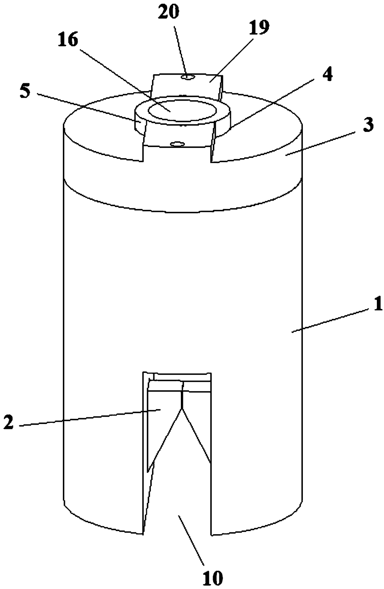
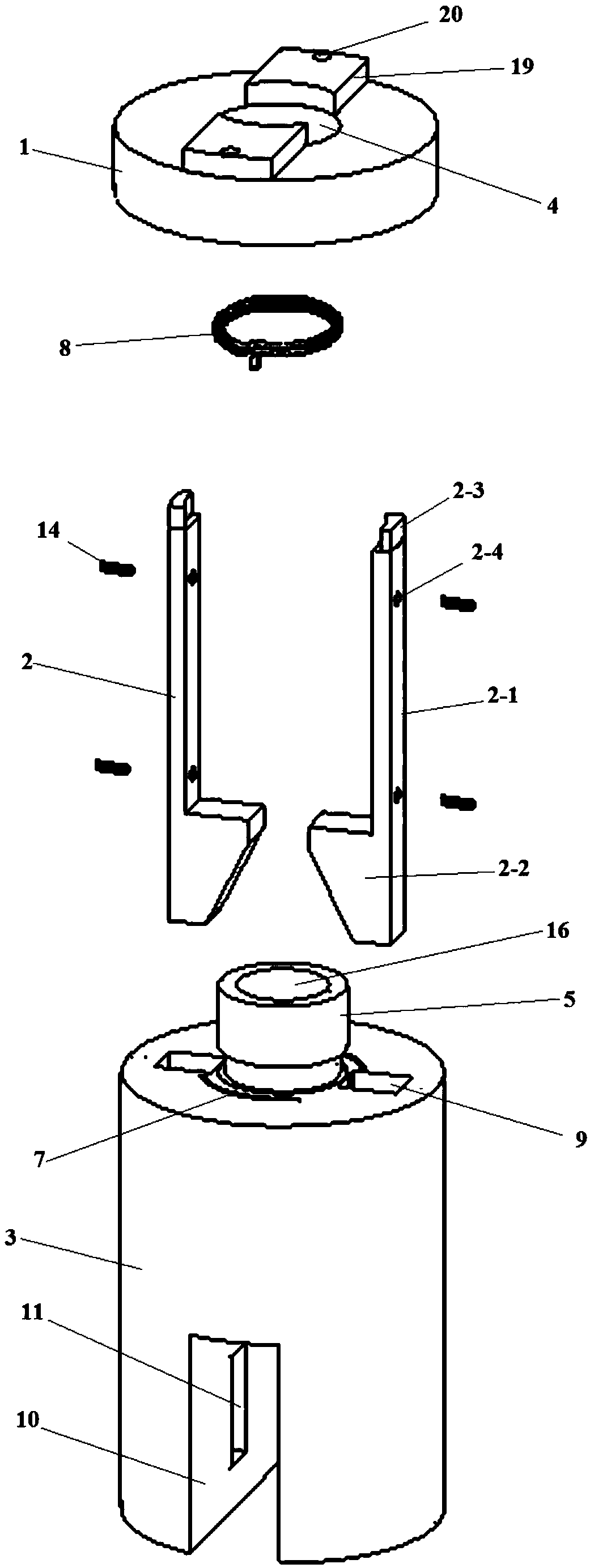
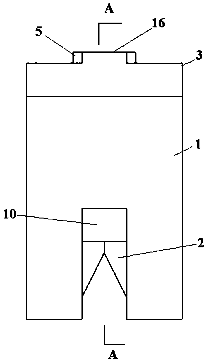
[0073] This embodiment provides a kind of self-locking lockset, such as Figure 1 to Figure 16 As shown, it includes a lock cylinder 1 and a lock tongue 2, and also includes a twist cover 3. A mounting hole 4 is processed in the center of the twist cover 3. A connecting post 5 is arranged at the center of the top of the lock cylinder 1, and the connecting post 5 is installed in the mounting hole. 4, the twist cover 3 can be rotated with the connecting column 5 as the center of rotation, a pair of connecting clips 6 are provided at the bottom of the twist cover 3, and a connecting slot 7 corresponding to the connecting clip 6 is provided at the top of the lock cylinder 1. The connecting card slot 7 is provided with the same diameter around the central axis of the lock cylinder 1, and the connecting card head 6 cooperates with the connecting card slot 7 to achieve a locked connection between the twist cover 3 and the lock cylinder 1 in the axial direction;

[0074] The connectin...

Embodiment 2

[0092] This embodiment provides a method of installation and construction of a self-locking lock and a few-shaped steel bar. The self-locking lock in this method adopts the self-locking lock in Example 1. Specifically, as Figure 21 to Figure 23 As shown, the method includes the following steps:

[0093] Step 1, making several-shaped reinforcing bars 21 and several-shaped reinforcing bar hole molds 22, said several-shaped reinforcing bars 21 comprising a pair of vertical reinforcing bars 21-1, a top transverse reinforcing bar 21-2 and a pair of bottom transverse reinforcing bars 21 -3, the tops of a pair of vertical steel bars 21-1 are respectively connected with one end of the top horizontal steel bar 21-2, and the bottom ends of a pair of vertical steel bars 21-1 are respectively connected with one end of a bottom horizontal steel bar 21-3; The horizontal reinforcement 21-2 is parallel to the bottom horizontal reinforcement 21-3, and the angle between the top horizontal reinfo...


PUM


Abstract

The invention provides a self-locking lockset and a method for installing and constructing several-shaped steel bars. The method includes the following steps: making several-shaped steel bars and several-shaped steel bar hole molds, and using the several-shaped steel bar hole molds to define several fonts The steel bars are bound together with the steel bars of the main structure, concrete is poured, and the mold is demoulded, and then lubricating oil is applied on the contact surface of the pair of lock heads of the lock tongue of the self-locking lock, and the self-locking lock is penetrated into the hole of the several-shaped steel bar In the process, let the deadbolt of the self-locking lock be connected with the several-shaped steel bar, and install the self-locking lock with the several-shaped steel bar. The installation and construction method of the present invention can form several-shaped steel bar holes through professional tools, and make the several-shaped steel bars can be located in the middle of the several-shaped steel bar holes, impartiality, and facilitate the quick connection with self-locking locks in the later stage. The steel bar and the self-locking lock are fast and convenient, and can realize the self-locking connection.

Description

technical field [0001] The invention belongs to the field of construction engineering and relates to locks, in particular to a self-locking lock suitable for the construction field and its application. Background technique [0002] The prefabricated building is a building that is assembled by dismantling the structural components of the building in advance and transporting them to the site through reliable connections after they are prefabricated in the factory. This kind of building is characterized by fast construction speed, less restricted by climatic conditions, labor saving, and improved building quality. The prefabricated shear wall structure is currently the most widely used prefabricated building in my country. [0003] However, there are still some problems in actual production. For example, the price of embedded connectors in prefabricated components is relatively high, and the operation of oblique supports on the construction site is difficult. At the same time, ...

Claims


Application Information

Patent Timeline
Patent Type & Authority Patents(China)
IPC IPC(8): E04G21/14
CPCE04G21/14
Inventor 赵平罗少帅张丽旸杨波涛姜圆圆杨祎宋晓芳陈阳
Owner XI'AN UNIVERSITY OF ARCHITECTURE AND TECHNOLOGY
Why Eureka
Try Eureka