
Steel structure beam column mortise-and-tenon-joint-type fast installing joint and installing method thereof

A steel structure, beam-column technology, applied in building structures, buildings, etc., can solve the problem of difficult construction of bolts in node areas, and achieve the effects of saving installation measures, improving buckling bearing capacity, and reasonable force transmission paths.

Inactive Publication Date: 2017-12-15
浙江中南绿建科技集团有限公司
View PDF0 Cites 10 Cited by
  • Summary
  • Abstract
  • Description
  • Claims
  • Application Information

AI Technical Summary

Problems solved by technology

[0004] The purpose of the present invention is to solve the above-mentioned technical problems existing in the prior art, and to provide a beam-column mortise-and-mortise quick-installation joint of a steel structure and its installation method. The construction of this joint is fast in place and has high installation accuracy, which makes the joint connection structure simpler , clear force transmission, fast construction, construction conditions are not affected by the working environment, reduce the construction cost of joints, and solve the problem that the bolts in the joint area are not easy to construct

Method used


Image

  • Steel structure beam column mortise-and-tenon-joint-type fast installing joint and installing method thereof
  • Steel structure beam column mortise-and-tenon-joint-type fast installing joint and installing method thereof
  • Steel structure beam column mortise-and-tenon-joint-type fast installing joint and installing method thereof

Examples


Embodiment Construction

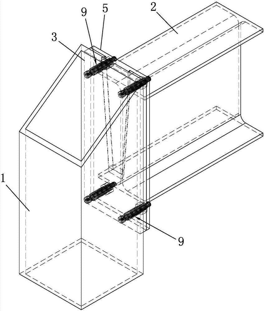
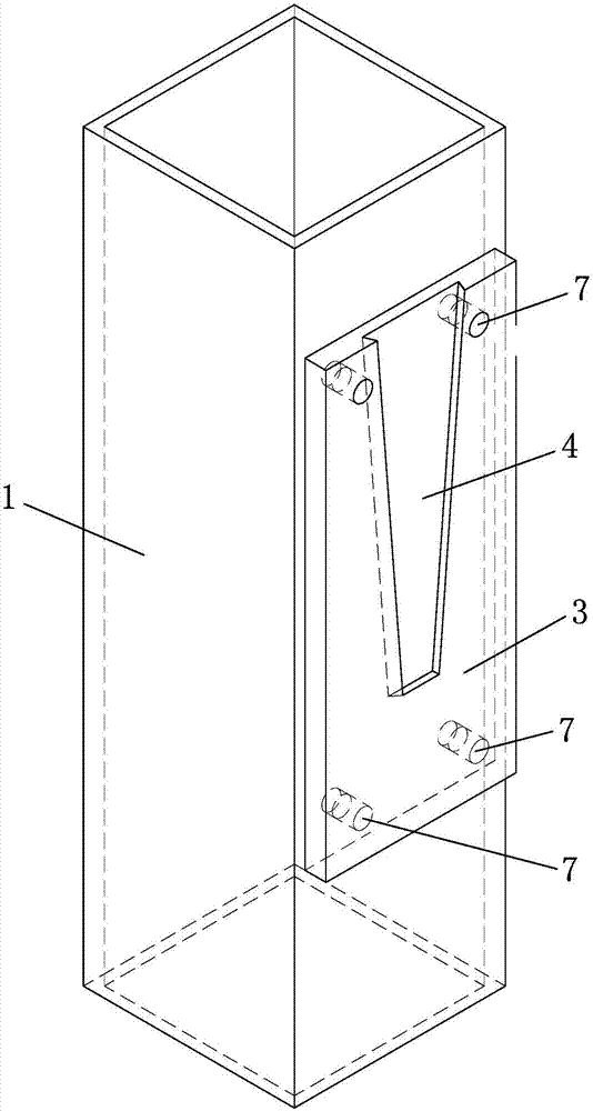
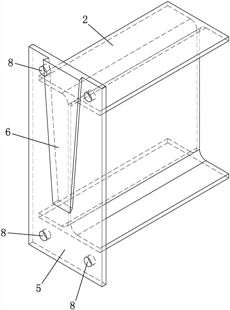
[0040] Such as Figure 1 to Figure 11 As shown, it is a steel structure beam-column mortise-and-tenon fast-installation joint in the present invention, including a steel pipe column 1 and a steel beam 2, and the steel pipe column 1 adopts one of cold-formed steel, welded steel and H-shaped steel column, which is convenient for steel pipe column 1 Use local materials to reduce costs. The steel girder 2 adopts one of H-shaped steel, I-beam, cold-formed rectangular pipe, and welded rectangular steel pipe, which is convenient for obtaining materials locally for the steel girder 2 and reduces costs.

[0041] The side of the steel pipe column 1 is welded with a reinforcement board 3 , the section width of the reinforcement board 3 is smaller than that of the steel pipe column 1 , and the reinforcement board 3 is provided with an embedding groove 4 . The end of the steel beam 2 is provided with an end plate 5 , the end plate 5 is provided with an embedded tenon 6 , the embedded teno...


PUM


Abstract

The invention discloses a steel structure beam column mortise-and-tenon-joint-type fast installing joint and an installing method thereof. The joint comprises a steel pipe column and a steel beam. The steel pipe column is provided with a reinforced attaching plate. An embedding groove is formed in the reinforced attaching plate. The steel beam is provided with an end plate. An embedded tenon is formed in the end plate. The embedded tenon is matched with the embedding groove. A self-locking bolt is arranged between a second bolt hole and a first bolt hole. The self-locking bolt comprises an outer bolt and an inner core bolt. The exterior of the outer bolt is provided with a hex nut. The end part of the outer bolt is provided with an internally-extending blade piece. The installing method comprises the following steps of (a) reinforced attaching plate machining, manufacturing and installing, (b) end plate machining, manufacturing and installing, (c) outer bolt and inner core bolt manufacturing, (d), steel pipe column and steel beam self-locking connecting, (e), self-locking bolt manufacturing, (f), steel pipe column and steel beam fastening and connecting, and (g), installing and detecting. The steel structure beam column mortise-and-tenon-joint-type fast installing joint has the characteristics that joint construction is fast in place, and the installing precision is high, a joint connecting structure is accurate in force transferring and fast and convenient to construct, and the problem that the bolt at a joint area is not easily constructed is solved.

Description

technical field [0001] The invention belongs to the technical field of assembled steel structures in construction engineering, and in particular relates to a beam-column mortise-and-mortise quick-installation joint of a steel structure and an installation method thereof. Background technique [0002] With the modernization of cities and towns and the rapid development of the national economy, the use of building functions has become increasingly complex. For multi-storey, high-rise, and super high-rise buildings, traditional concrete structures or pure steel structures have been difficult to meet the functional requirements. Concrete-filled steel tube columns are increasingly used in building structures due to their excellent performance. Research on a more reasonable connection form between concrete-filled steel tube columns and steel beams is a focus of current prefabricated steel structure technology research. [0003] At present, the joints between concrete filled steel ...

Claims


Application Information

Patent Timeline
Patent Type & Authority Applications(China)
IPC IPC(8): E04B1/30E04B1/58B23P15/00
CPCE04B1/30B23P15/00E04B1/5812E04B2001/5881E04B2001/5887
Inventor 王宇伟夏念涛夏伟平费建伟刘海孙庆洪沈学柱
Owner 浙江中南绿建科技集团有限公司
Learn More