
Spherical butterfly valve

A butterfly valve and spherical technology, applied in the field of spherical butterfly valves, can solve the problems of affecting medium parameters, local uneven thickness of the valve body wall, reduced valve flow capacity, etc. The effect of improving the flow capacity

Pending Publication Date: 2018-09-21
郑州铝都阀门有限公司
View PDF0 Cites 1 Cited by
  • Summary
  • Abstract
  • Description
  • Claims
  • Application Information

AI Technical Summary

Problems solved by technology

The valve seat pressure ring is a flange structure. In order to ensure the reasonable design of the valve body structure and size, the valve seat pressure ring must be designed with a reduced diameter, otherwise the wall thickness of the valve body will be partially uneven, resulting in casting defects in the design. Due to the reduced diameter design of this structure, the flow capacity of the valve will be reduced. For the water system, this structure will affect the medium parameters of the downstream process system on site

Method used


Image

  • Spherical butterfly valve
  • Spherical butterfly valve
  • Spherical butterfly valve

Examples


Embodiment 1

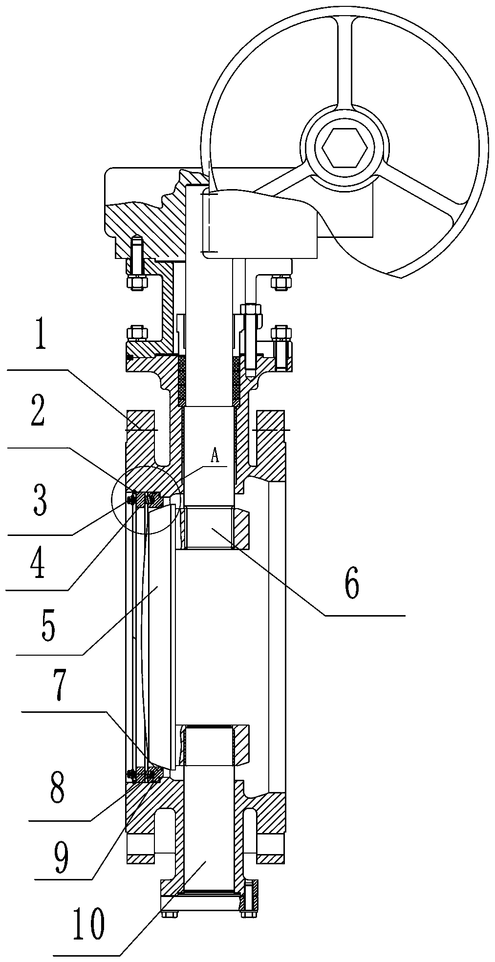
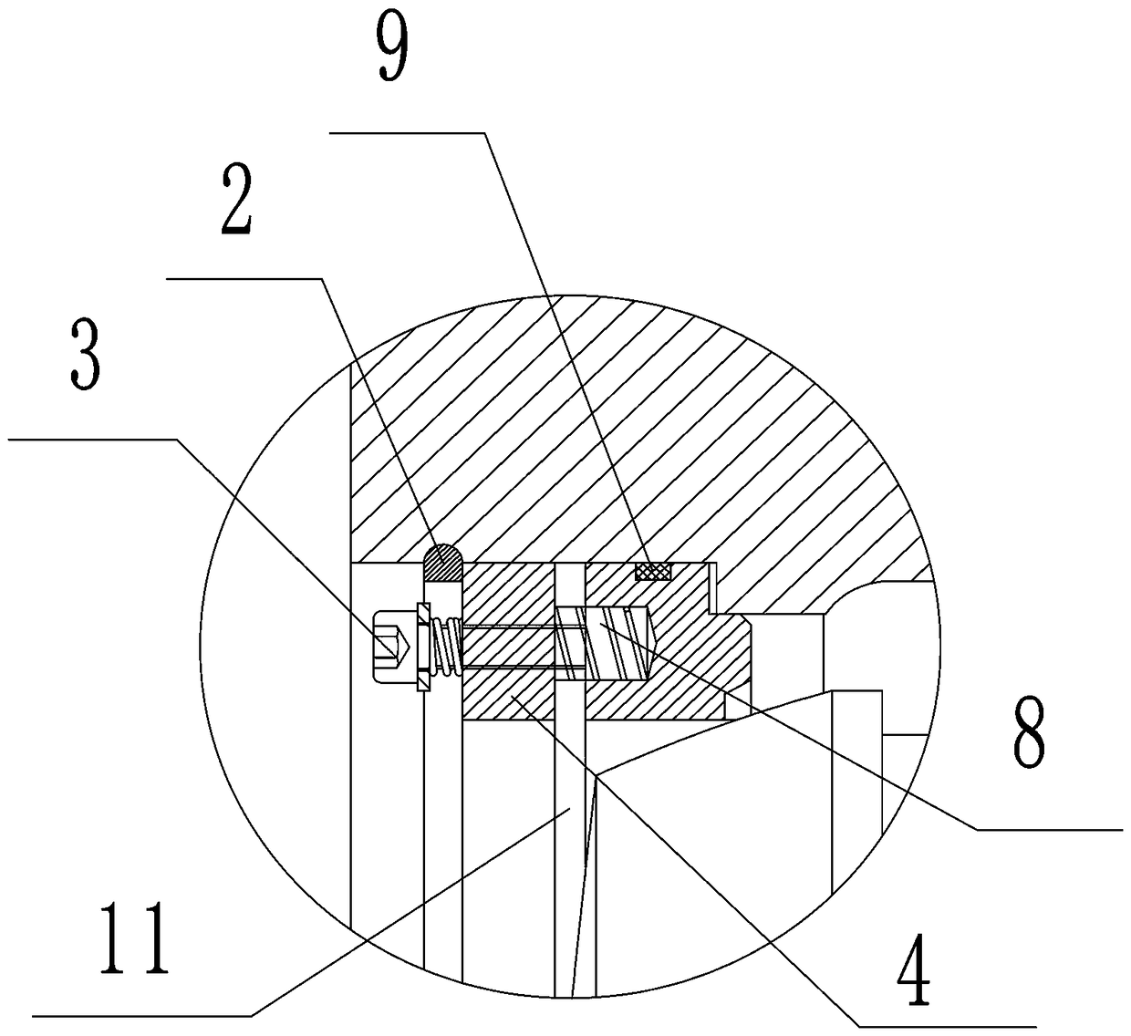
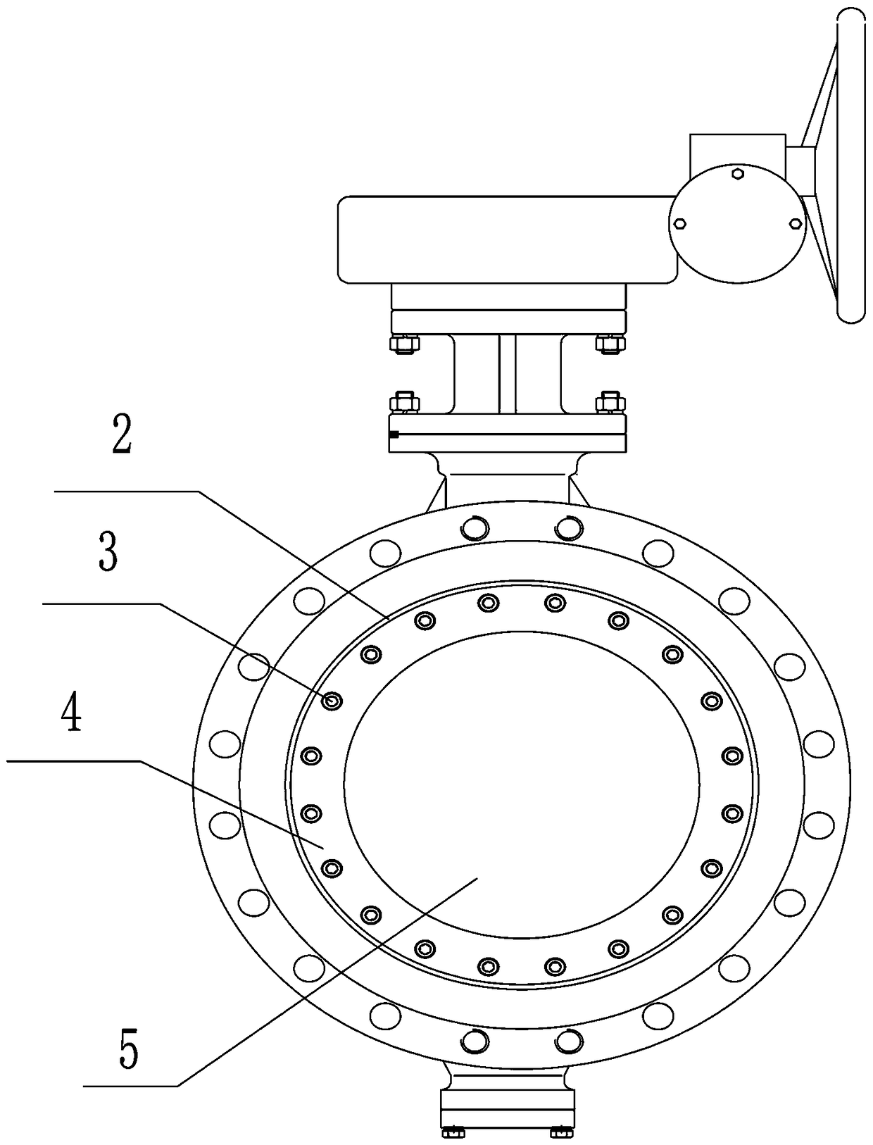
[0023] This embodiment provides a spherical butterfly valve, such as figure 1 , figure 2 and image 3 As shown, it includes a driving device, a valve body 1, a valve shaft, a valve seat 7 and a valve plate 5. The valve body 1 is provided with a cavity for accommodating the valve plate 5, and the valve plate 5 is movably arranged in the cavity. In the chamber, the valve shaft is eccentrically connected to the valve plate 5, and the driving device drives the valve plate 5 to rotate through the valve shaft.

[0024] Specifically, the valve seat 7 is provided with a sealing ring 9, and the valve seat 7 is sealed on the inner wall of the cavity through the sealing ring 9, and the valve plate 5 and the valve seat 7 form a dynamic sealing pair. .

[0025] A valve seat retainer 4 for pressing the valve seat 7 and a valve seat retainer 2 for restricting the valve seat retainer 4 are also arranged on the inner wall of the cavity. The outer edge of the valve seat retainer ring 2 is ...


PUM


Abstract

The invention provides a spherical butterfly valve. The spherical butterfly valve comprises a driving device, a valve body, a valve shaft, a valve seat and a valve plate; a cavity used for containingthe valve plate is formed in the valve body, the valve plate is movably arranged in the cavity, the valve shaft is eccentrically connected with the valve plate, a step used for mounting the valve seatis arranged on the inner wall of the cavity, the valve seat is arranged on the step in a sealed mode, the valve plate and the valve seat form a dynamic sealing pair, and a valve seat pressing ring and a valve seat pressing ring baffle ring are arranged on the inner wall of the cavity; a compensation gap is left between the valve seat and the valve seat pressing ring; and a pre-fastening screw used for jacking and pressing the valve seat is arranged on the valve seat pressing ring, and the bottom end of the pre-fastening screw abuts against the valve seat. The spherical butterfly valve is compact in structure and easy to machine, and meanwhile has the advantages that the valve is convenient to mount and maintain, the sealing property is good, the reliability is high, online repairing can be conducted, and aboveground operation can be conducted conveniently.

Description

technical field [0001] The invention relates to a valve, in particular to a spherical butterfly valve. Background technique [0002] The spherical butterfly valve is a valve with a butterfly valve structure and a spherical sealing pair, that is, the sealing surface of the valve plate is a spherical surface, and the sealing surface of the valve seat is a conical surface. The spherical butterfly valve is a double eccentric structure, using the principle of sealing pair wedge, when the valve is closed, it can cut off the dirt or dirt deposited on the sealing surface of the valve plate, so as to ensure the cleaning of the sealing surface. The spherical butterfly valve currently used in the market is mainly composed of main parts such as valve body, valve seat pressure ring, valve seat, valve plate, valve seat sealing ring, upper and lower valve shafts. The seal between the valve seat and the valve body mainly has two forms: end face seal and radial seal. The radial seal can rea...

Claims


Application Information

Patent Timeline
IPC IPC(8): F16K1/226F16K1/32F16K31/60
CPCF16K1/2263F16K1/2266F16K1/32F16K31/60
Inventor 王帅张嘉伦
Owner 郑州铝都阀门有限公司
Learn More