Array wind speed and direction sensor and manufacturing method thereof
A wind speed, wind direction, and sensor technology, which is applied in the direction of instruments, indicating/recording actions, and using thermal variables to measure fluid speed, etc., can solve the problems of difficult volume reduction, high price, and heavy weight, so as to reduce the deviation of measured wind speed and structure Simple, low-cost effect
- Summary
- Abstract
- Description
- Claims
- Application Information
AI Technical Summary
Benefits of technology
Problems solved by technology
Method used
Image
Examples
Embodiment 1
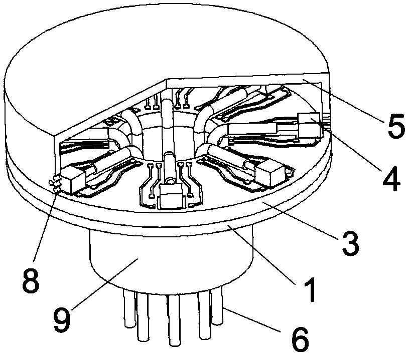
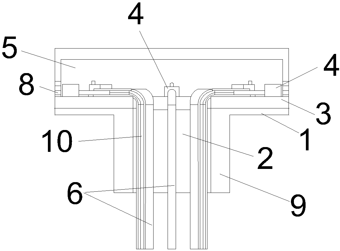
[0050] Example 1, such as figure 1 and figure 2 As shown, the array wind speed and direction sensor provided by the present invention,
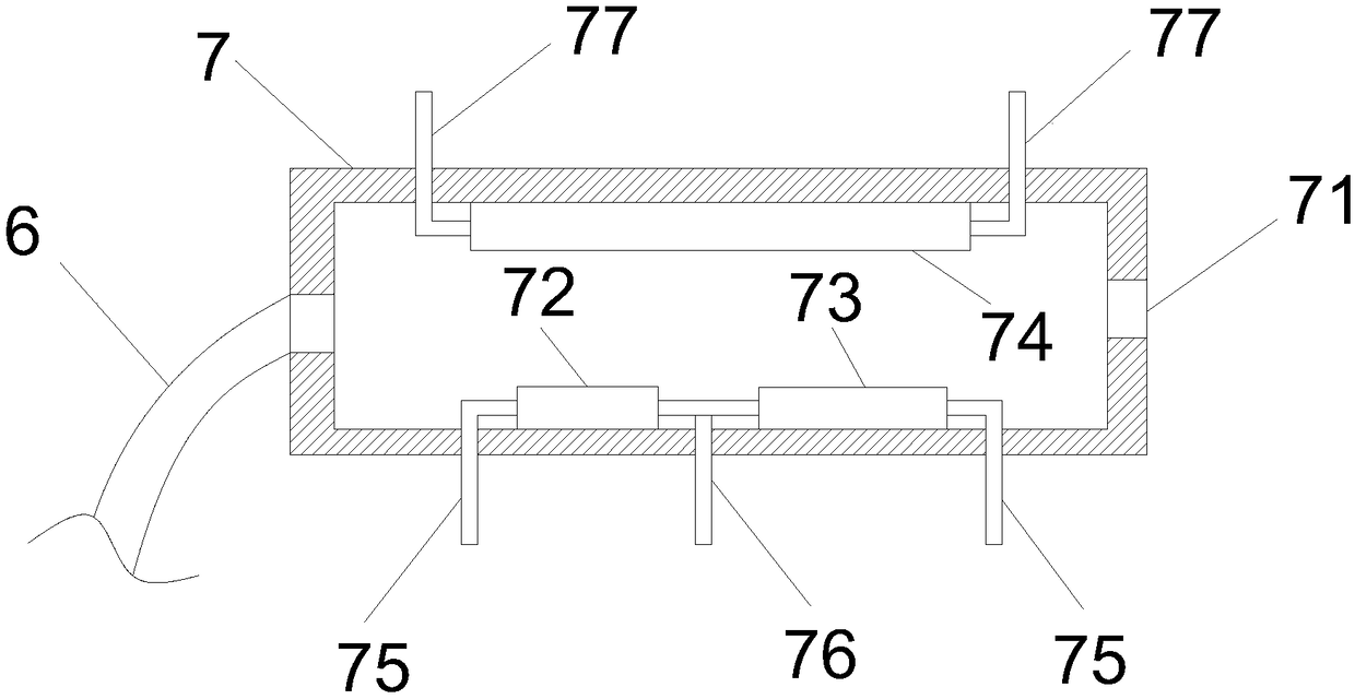
[0051] It includes an upper cover 5 and a bracket 1 that are fastened together. After the upper cover 5 and the bracket 1 are fastened together, they can also be sealed by glue; the bracket 1 is provided with a ceramic circuit board 3, and the center of the bracket 1 is provided with a second Two air pipes 9, the second air pipe 9 is a hollow round pipe, which can lead out the lead wires of the thermal sensitive flow chip 4 to facilitate the assembly of the sensor. The ceramic circuit board 3 is provided with a plurality of thermal sensitive flow chips 4 A plurality of thermal sensitive flow chips form an array structure, generally in an annular array structure, and the positions of the plurality of thermal sensitive flow chips 4 are set opposite to the plurality of vent holes 8 on the upper cover 5 one by one. The first air pipe 6 of the ...
Embodiment 2
[0088] The present invention also provides a method for manufacturing the aforementioned array wind speed and direction sensor, the method comprising:
[0089] Step 1) First, adopt mechanical processing to make a bracket 1 made of stainless steel or aluminum alloy. The bracket 1 is a circular structure, and a round hole 2 is processed in the middle of the circular structure. The bracket 1 includes two parts, one part is hollow Circular structure, the side of the circular structure is the side wall, the thickness of the side wall is 2-4mm, the diameter is 30-40mm, the other part is a circular tube structure, the thickness is 2-4mm, and the inner diameter of the tube is 10-15mm;
[0090] Step 2) Manufacturing steps of ceramic circuit board 3: ceramic circuit board 3 is made of alumina material, and the metal wiring for signal transmission is the metal wiring on the ceramic board connected to the solder pins and outer leads of the sensitive chip tube shell, and the metal wiring is...
PUM
| Property | Measurement | Unit |
|---|---|---|
| Thickness | aaaaa | aaaaa |
| Diameter | aaaaa | aaaaa |
| The inside diameter of | aaaaa | aaaaa |
Abstract
Description
Claims
Application Information
 - R&D
- Intellectual Property
- Life Sciences
- Materials
- Tech Scout
- Unparalleled Data Quality
- Higher Quality Content
- 60% Fewer Hallucinations
Browse by: Latest US Patents, China's latest patents, Technical Efficacy Thesaurus, Application Domain, Technology Topic, Popular Technical Reports.
© 2025 PatSnap. All rights reserved.Legal|Privacy policy|Modern Slavery Act Transparency Statement|Sitemap|About US| Contact US: help@patsnap.com


