Photovoltaic Blind

Inactive Publication Date: 2014-01-30
ILAND GREEN TECH
View PDF40 Cites 19 Cited by
  • Summary
  • Abstract
  • Description
  • Claims
  • Application Information

AI Technical Summary

Benefits of technology

[0024]In order to prevent excessive direct currents from circulating, individual circuit breakers

Problems solved by technology

The surface available for the solar cells is limited and the produced energy therefore reduced.
Furthermore, the electric connection between the photoelectric cells and the blind's motor or the other electric

Method used


Image

  • Photovoltaic Blind
  • Photovoltaic Blind
  • Photovoltaic Blind

Examples


Embodiment Construction

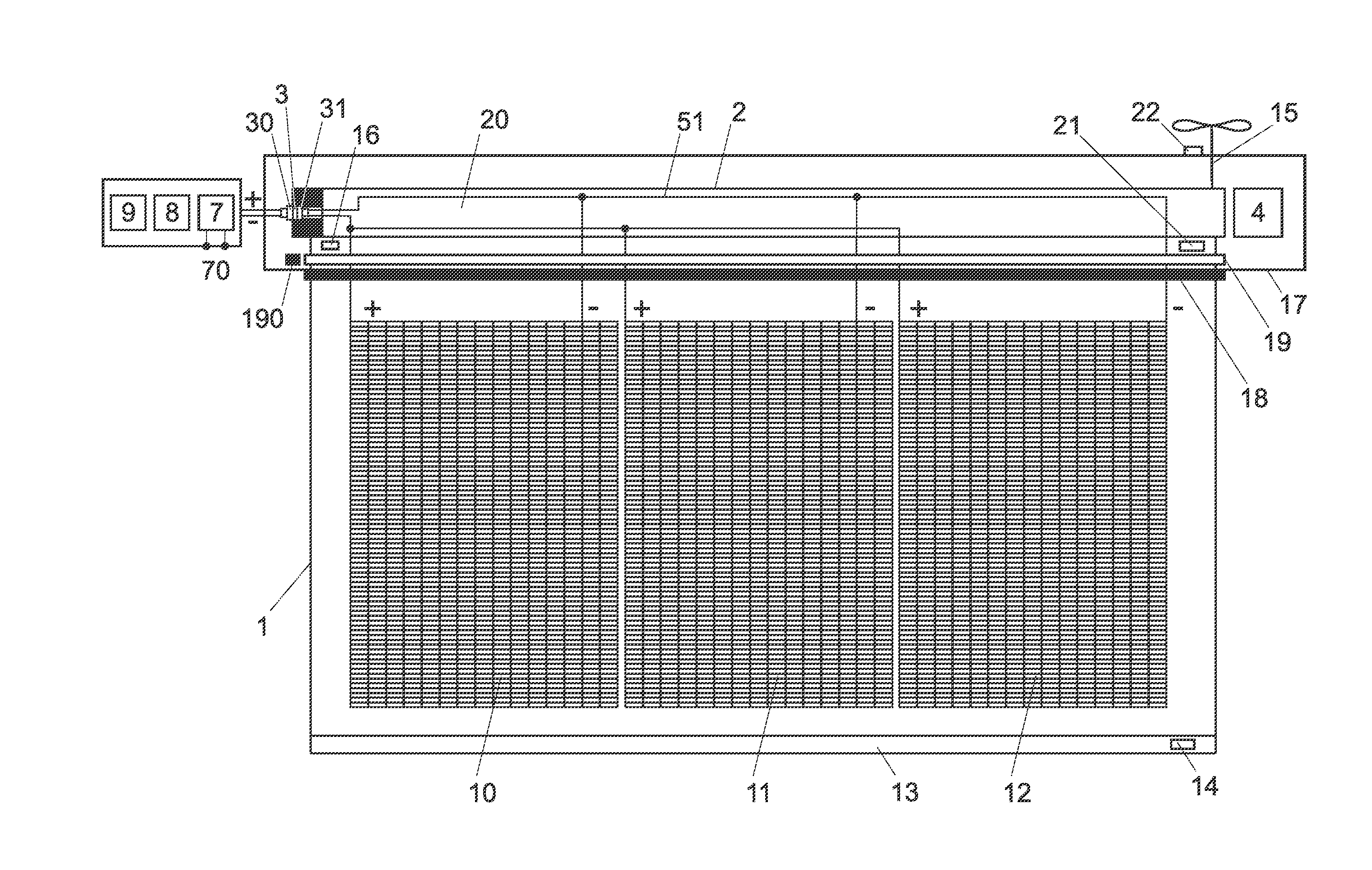
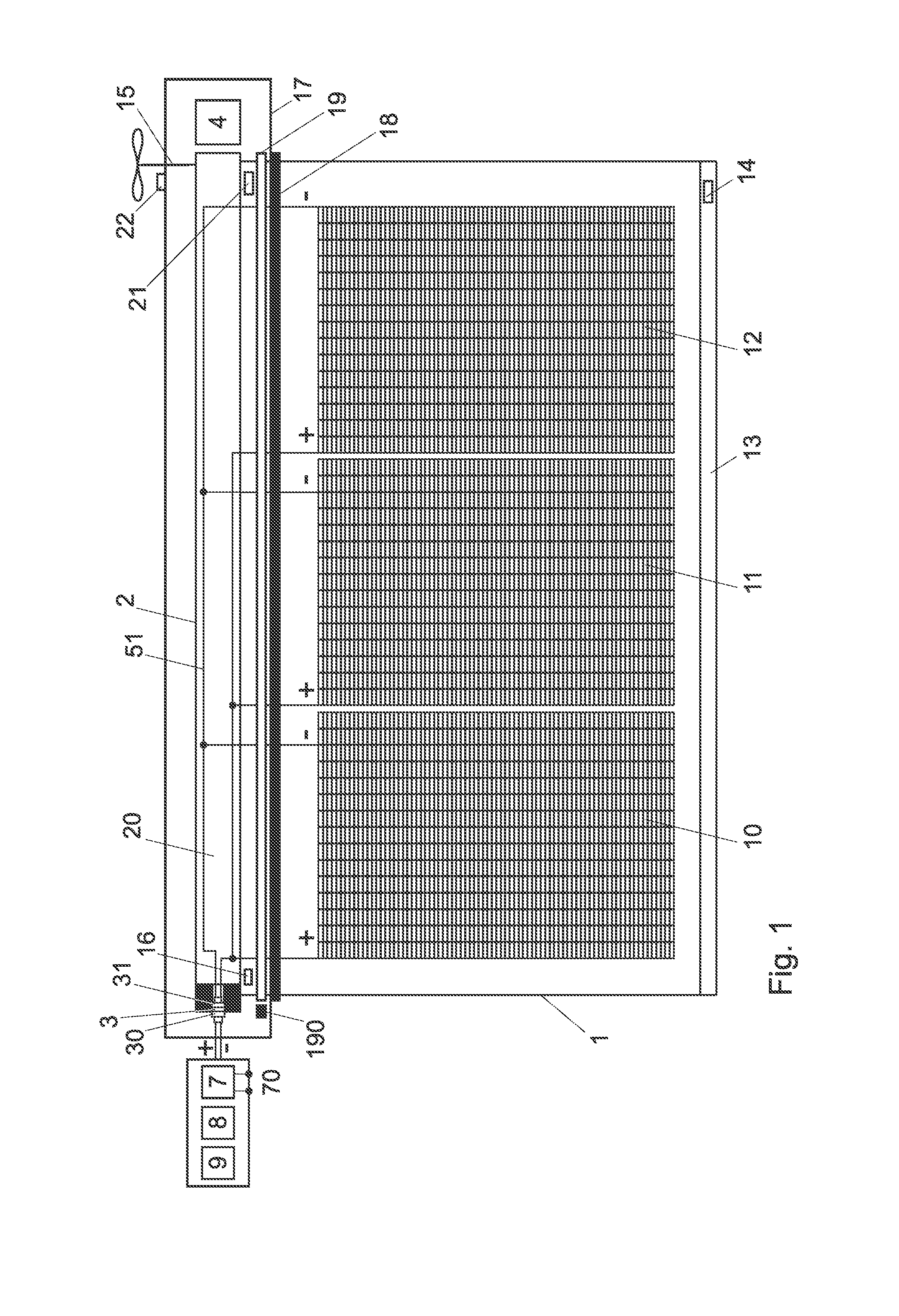
[0028]The photovoltaic blind 1 illustrated in the figures comprises a cloth onto which are mounted one or several flexible photovoltaic panels, in this example three panels 10 to 12 that can be welded to one another or glued onto a support. A greater number of panels can be provided. A loadbar 13 is mounted on the distal extremity of the blind, whose weight tends to make the blind unroll. The blind can be rolled or unrolled around a rotating drum 2, or roller, for example manually by means of a bar, not represented, and / or by means of an electric motor at one of the ends of the rotating drum 2. Arms, not represented, are advantageously provided under the blind in order to stretch out the cloth between the axis 2 and the loadbar 13, for example joint-arms at each left-right end of the cloth or horizontal arms from the loadbar towards the wall.

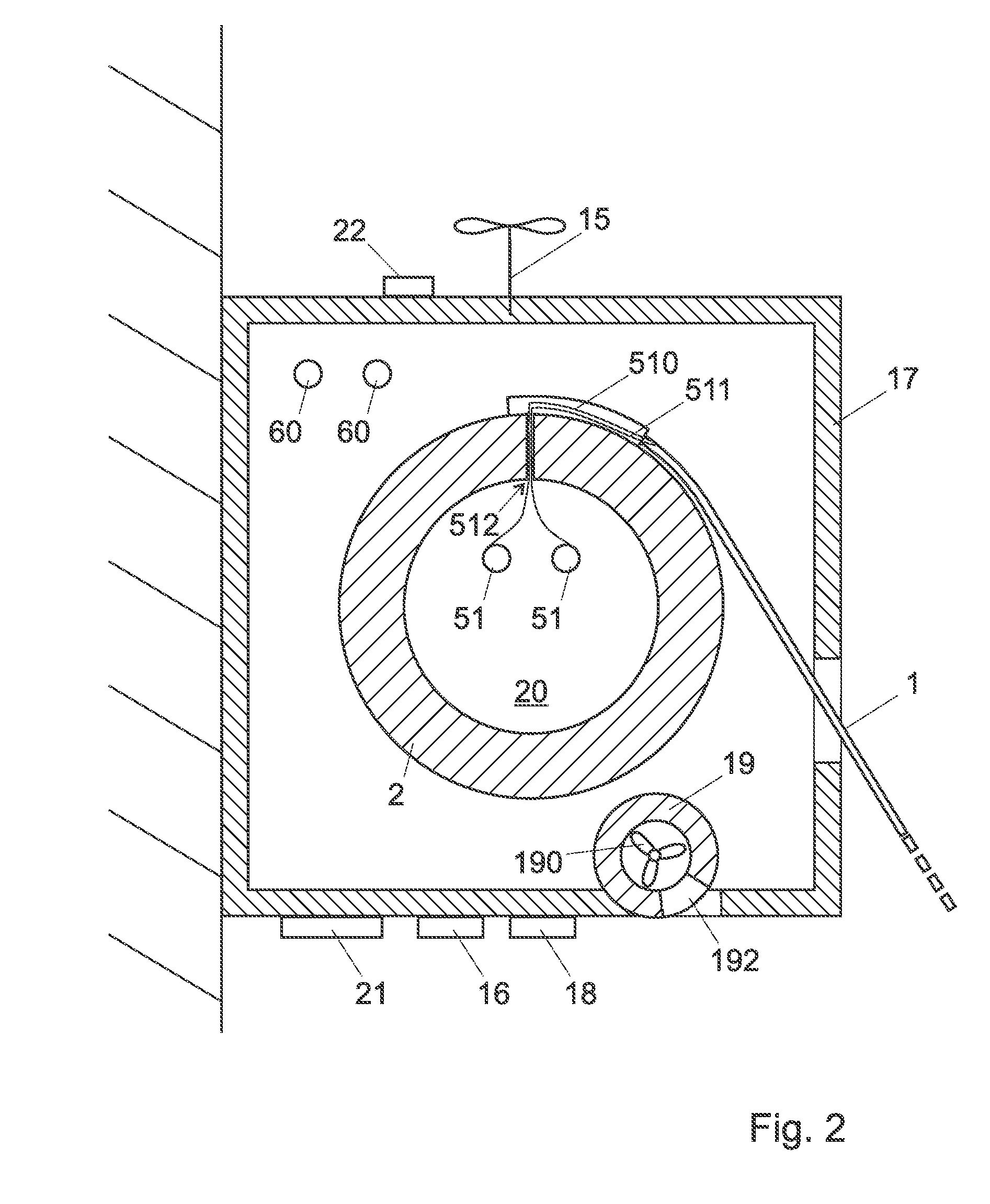
[0029]The rotating drum 2 at the proximal extremity of the photovoltaic blind 1 is mounted in a cassette 17, for example a stainless steel cass...


PUM


Abstract

The invention relates to a photovoltaic blind (1) comprising a rotating drum (2) and several flexible photovoltaic panels (10-12) that can be rolled up and unrolled around this rotating drum to close respectively unfold the blind. The device comprises a ventilation tube (19) and a ventilator (190) powered by the photovoltaic panels in order to create an air flux under the photovoltaic blind.

Description

[0001]The present application claims priority of Swiss patent application CH2012 / 1113, filed on Jul. 24, 2012, the contents of which is hereby enclosed by reference.TECHNICAL FIELD[0002]The present invention relates to a photovoltaic blinds / roller shutter, in particular a rollable photovoltaic blind with flexible photovoltaic panels.[0003]The invention relates in particular to a joint-arm blind designed to be fastened onto a building wall, for example to protect a terrace from the sun, and which can be either rolled into a cassette mounted against or inside the wall or unfolded obliquely above the terrace. Such blinds are also known under the name of standout blinds, awnings or canopies, depending on the type of arm connecting the roller blind header to the cassette.STATE OF THE ART[0004]It is already known in the state of the art to use the surface of blinds to produce electricity.[0005]EP1845218A2 describes a motorized blind with photovoltaic panels mounted onto the box into which...

Claims


Application Information

Patent Timeline
IPC IPC(8): E06B9/40
CPCE06B9/40E06B2009/2476H02S30/20Y02E10/50
Inventor OPPIZZI, DANIELE
Owner ILAND GREEN TECH
Why Eureka
Try Eureka