An image acquisition and processing device and method
An image acquisition and processing, image technology, applied in the field of image processing, can solve the problems of poor image fusion effect, small acquisition range, etc.
- Summary
- Abstract
- Description
- Claims
- Application Information
AI Technical Summary
Problems solved by technology
Method used
Image
Examples
Embodiment 1
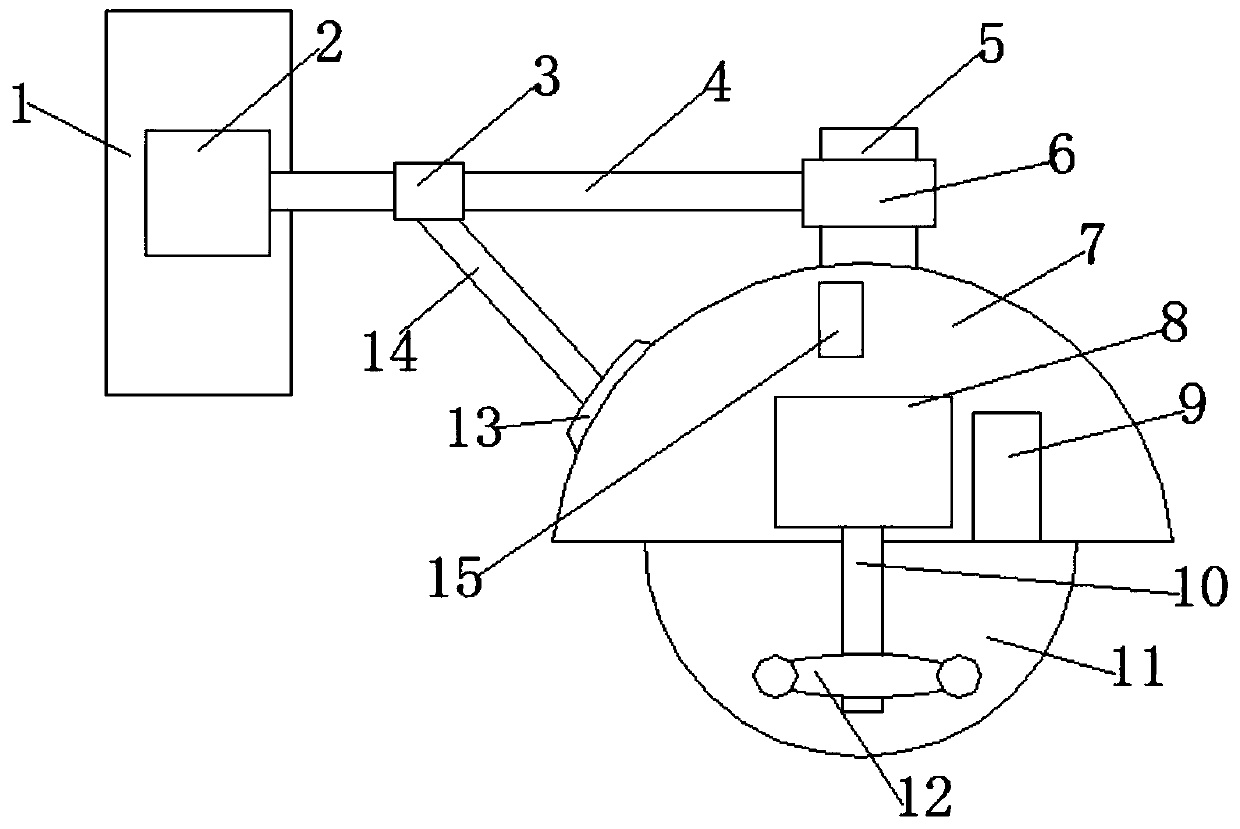
[0062] The image acquisition and processing device of the present embodiment 1 includes a first motor 2, a first transmission shaft 4 is screwed on the end of the first motor 2, and a first transmission shaft 4 is screwed on the other end of the first transmission shaft 4. There is a ring-shaped rotating ring 6, and a second adjusting seat 5 is pivotally connected to it along the axial direction of the rotating ring 6, and a hemispherical shell 7 is hinged at the lower end of the second adjusting seat 5 ; A first motor driver is electrically connected to the first motor 2;
[0063] A hemispherical glass cover 11 is threaded on the lower side of the housing 7; a second motor 8 is fixed to the inner bolt of the housing 7, and a DSP controller 9 is clamped in the housing 7. The DSP controller 9 is electrically connected to the second motor 8; the second motor driver is electrically connected to the second motor 8;
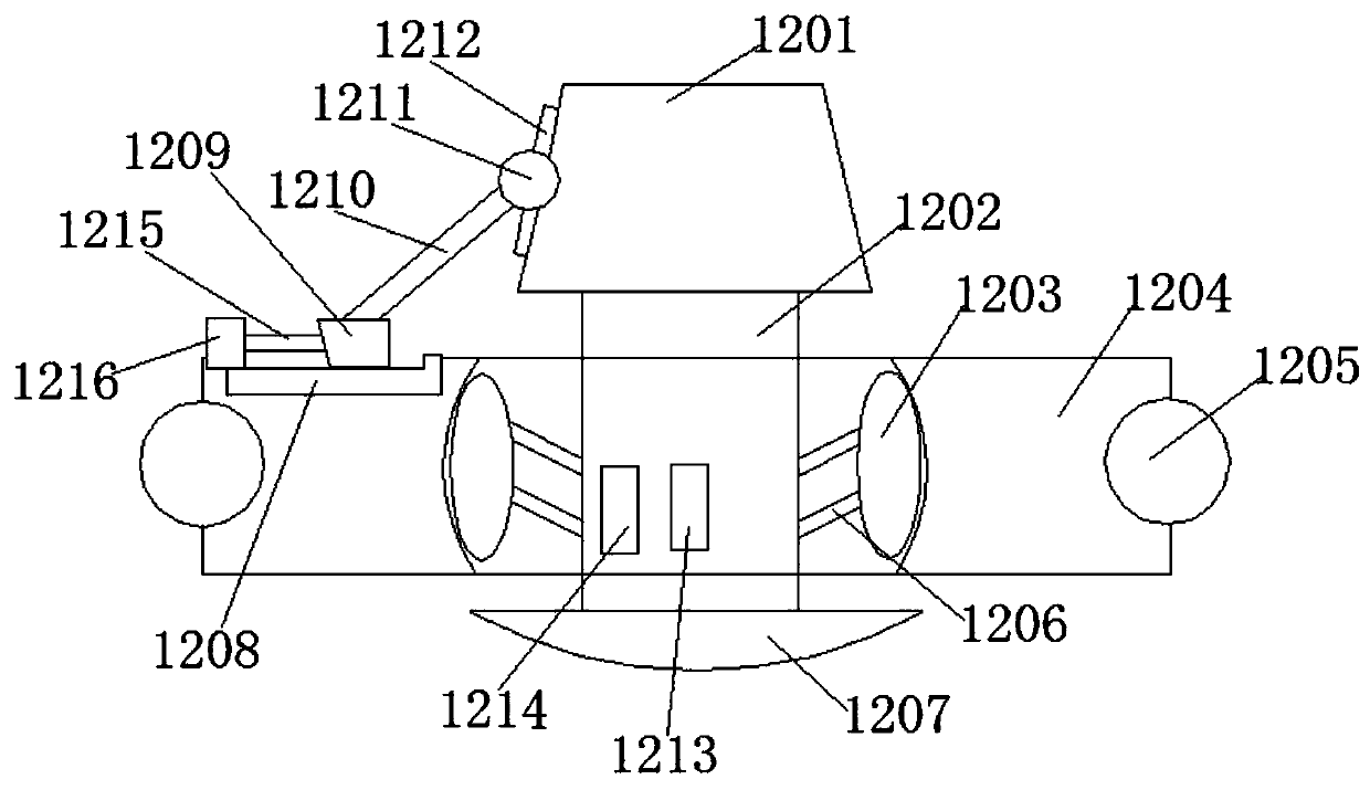
[0064] Along the radial direction of the housing 7, a round bar...
Embodiment 2
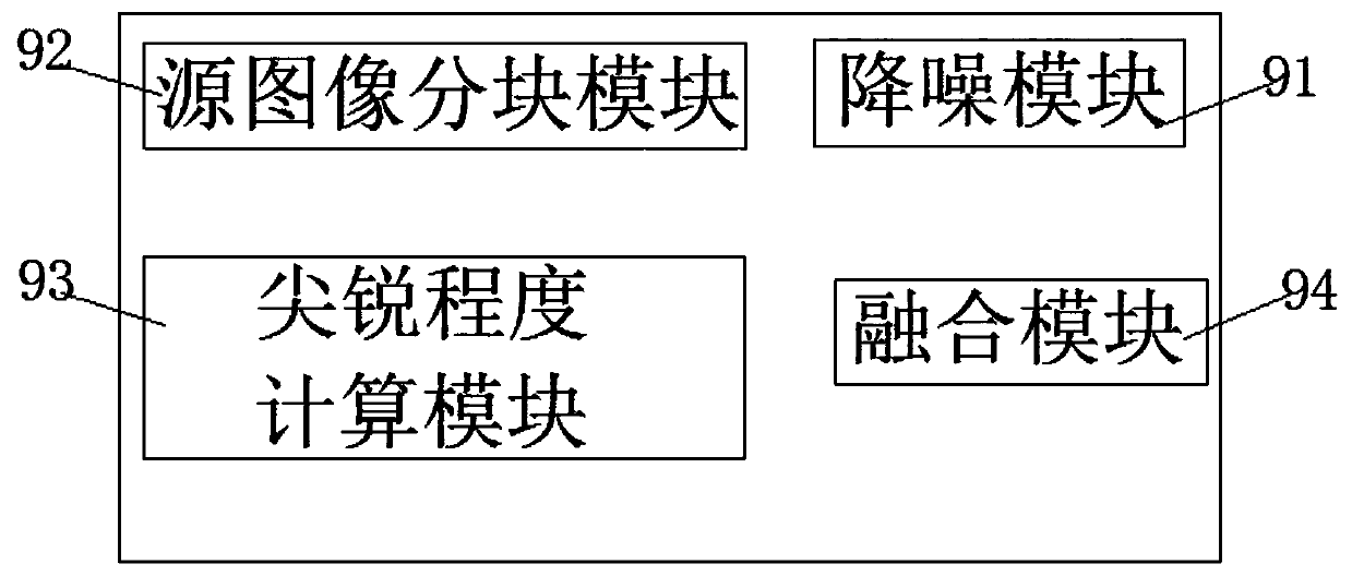
[0080] The noise reduction module 91 includes a detection unit and a filter noise reduction unit;
[0081] The detection unit is used to detect a frequency band range of noise in the selected image;
[0082] The filtering and denoising unit is used to select a corresponding image filtering method according to the frequency band range to perform filtering and denoising processing on noise so as to improve the signal-to-noise ratio of the image.
[0083] The source image block module 92 includes a first parameter setting unit, a second parameter setting unit, an image selection unit and an image cutting unit;
[0084] The first parameter setting unit is used to set the number m of source images for image fusion, where m is greater than or equal to 2;
[0085] The second parameter setting unit is used to set the number of dimensions n when performing image slicing, and the n is greater than or equal to 3;
[0086] The image selection unit is used to select images that require i...
Embodiment 3
[0106] An image acquisition and processing method, using the image acquisition and processing device,
[0107] Step 1: setting the first rotation angle a, the second rotation angle b and the first tilt angle c through the DSP controller 9;
[0108] Step 2: the DSP controller 9 sends a rotation command to the first motor driver, and the first motor driver drives the first motor 2 to rotate;
[0109] Step 3: the first transmission shaft 4 rotates and drives the housing 7 to rotate, the third angle sensor 15 detects the first actual rotation angle a1 of the housing 7 and sends it to the DSP controller 9;
[0110] Step 4: if a1 is less than a, then the DSP controller 9 sends a command to continue rotating to the first motor driver; if a1 is equal to a, then the DSP controller 9 sends a command to stop rotating to the first motor driver, At the same time, the DSP controller 9 accumulates the multiple actual rotation angles of the first motor 2;
[0111] Step 5: the DSP controller...
PUM
 Abstract
Description
Claims
Application Information
 - R&D
- Intellectual Property
- Life Sciences
- Materials
- Tech Scout
- Unparalleled Data Quality
- Higher Quality Content
- 60% Fewer Hallucinations
Browse by: Latest US Patents, China's latest patents, Technical Efficacy Thesaurus, Application Domain, Technology Topic, Popular Technical Reports.
© 2025 PatSnap. All rights reserved.Legal|Privacy policy|Modern Slavery Act Transparency Statement|Sitemap|About US| Contact US: help@patsnap.com


