Adjustable portal assembly for forklift

An adjustable, gantry technology, applied in the direction of lifting devices, etc., can solve the problem that the fork legs cannot be adjusted automatically, and achieve the effects of improving work stability, improving use efficiency and ingenious structure.

Pending Publication Date: 2018-09-25
三门华和智能科技有限责任公司
View PDF16 Cites 1 Cited by
  • Summary
  • Abstract
  • Description
  • Claims
  • Application Information

AI Technical Summary

Problems solved by technology

[0005] The purpose of the present invention is to address the deficiencies of the prior art, by setting the adjusting mechanism to cooperate with the scissors mechanism, adjusting the optimal material insertion position through the actual working condition adjustment mechanism, synchronously driving the scissors mechanism to adjust to the optimal angle, and then cooperating The stable mechanism solves the technical problem that the fork legs cannot be automatically adjusted for goods of different specifications and sizes when carrying goods, so that it can achieve clamping and stabilization effects on materials of various specifications and positions

Method used


Image

  • Adjustable portal assembly for forklift
  • Adjustable portal assembly for forklift
  • Adjustable portal assembly for forklift

Examples


Embodiment 1

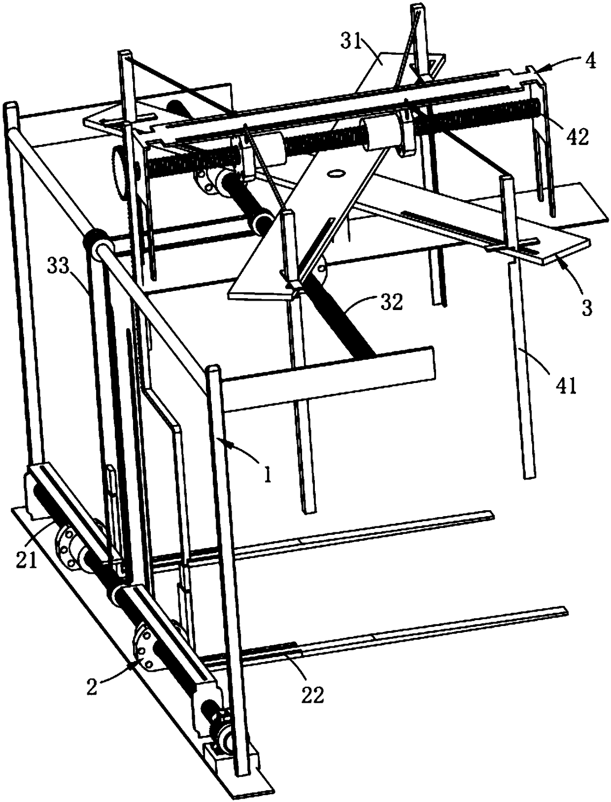
[0069] Such as figure 1 As shown, an adjustable mast assembly for a forklift, including a frame 1, also includes:

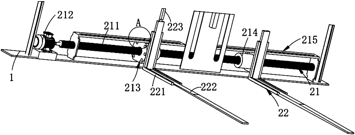
[0070] An adjustment mechanism 2, the adjustment frame 1 is installed on the frame 1, which includes a control assembly a21 arranged above the frame 1 and a lifting mechanism fixedly connected to the control assembly a21 and located on one side thereof component 22;

[0071] The scissors mechanism 3, the scissors mechanism 3 is located on the side of the adjustment mechanism 2 and arranged above the lifting assembly 22, which includes a cross assembly 31 synchronously driven with the lifting assembly 22, slidingly arranged on the cross A control assembly b32 on and below the assembly 31 and a transmission assembly 33 connected to the control assembly b32 at one end and connected to the control assembly a21 at the other end; and

[0072] The stabilizing mechanism 4, the stabilizing mechanism 4 is arranged above the scissor mechanism 3, which includes a tightenin...

Embodiment 2

[0119] Components that are the same as or corresponding to those in the first embodiment use the reference numerals corresponding to those in the first embodiment. For the sake of simplicity, only the differences from the first embodiment are described below. The difference between this embodiment two and embodiment one is:

[0120] Further, the height difference between the rotating shaft a3243 and the rotating shaft b3253 is H1, the thickness difference between the first cross plate 313 and the second cross plate 314 is H2, the angle iron a413 and the The height difference between the angle iron b418 is H3, said H1=H2=H3.

[0121] In this embodiment, since the first crossing plate 313 and the second crossing plate 314 are set up and down, by setting H1=H2=H3, on the one hand, the lower ends of the angle iron a413 and the angle iron b418 are flush with each other while ensuring that they are respectively The connecting rod a415 and connecting rod b419 hinged at the upper end...


PUM


Abstract

The invention relates to an adjustable portal assembly for a forklift. The assembly comprises a rack and also comprises an adjusting mechanism, a scissors fork mechanism and a stabilizing mechanism, wherein the adjusting rack is mounted on the rack and comprises a control assembly a and a lifting assembly fixedly connected to the control assembly a and located on one side of the control assembly a; the scissors fork mechanism is located on one side of the adjusting mechanism and is located above the lifting assembly and comprises a cross assembly synchronously driven together with the liftingassembly, a control assembly b slidably arranged on the cross assembly and located below the cross assembly and a driving assembly, one end of which is connected to the control assembly b while the other end of which is connected to the control assembly a; and the stabilizing mechanism is arranged above the scissors fork mechanism and comprises a tightening assembly slidably arranged on the crossassembly and a control assembly c for controlling the tightening assembly to fold and release. The assembly solves the technical problem that a fork leg cannot be adjusted automatically for carrying cargoes of different specifications and sizes, so that the assembly further achieves the effects of clamping and stabilizing materials of various specifications and in different positions.

Description

technical field [0001] The invention relates to the technical field of forklifts, in particular to an adjustable mast assembly for a forklift. Background technique [0002] When moving goods in a short distance, such as moving goods from a truck to a shelf, or moving goods from a shelf to a truck, a forklift is often needed. The forklift is convenient and fast to carry, and the labor intensity of the operator is low. An important part of the forklift structure, the lifting and handling of goods is completed by the controller driving the lifting parts. Therefore, the quality of forklift lifting components directly affects the overall performance of the forklift structure. In the prior art, the maneuverability and safety of many forklift structures are poor, resulting in potential safety hazards in the forklift structure when handling goods, causing inconvenience to the work of handling goods or causing injury to the handling personnel. [0003] The patent document with the ...

Claims


Application Information

Patent Timeline
Patent Type & Authority Applications(China)
IPC IPC(8): B66F9/08B66F9/24B66F9/20B66F9/075
CPCB66F9/07504B66F9/08B66F9/20B66F9/24
Inventor 施华平
Owner 三门华和智能科技有限责任公司
Why Eureka
Try Eureka