Communication pipe traction line device

A technology of pulling wires and pipes, which is applied in the direction of cable installation devices, cable installation, optical fiber/cable installation, etc. It can solve problems such as failure to operate normally, achieve a wide range of applications, improve the effect of threading, and prevent overturning

Pending Publication Date: 2018-09-25
NANJING LONGMA COMM ENG CO LTD
View PDF9 Cites 8 Cited by
  • Summary
  • Abstract
  • Description
  • Claims
  • Application Information

AI Technical Summary

Problems solved by technology

[0004] When routing a duct with an existing optical cable inside, the deployer will interfere with the optical cable in the duct and cannot operate normally
Therefore, the above-mentioned applicators are only suitable for the routing of leads in new pipes

Method used


Image

  • Communication pipe traction line device
  • Communication pipe traction line device
  • Communication pipe traction line device

Examples


Embodiment

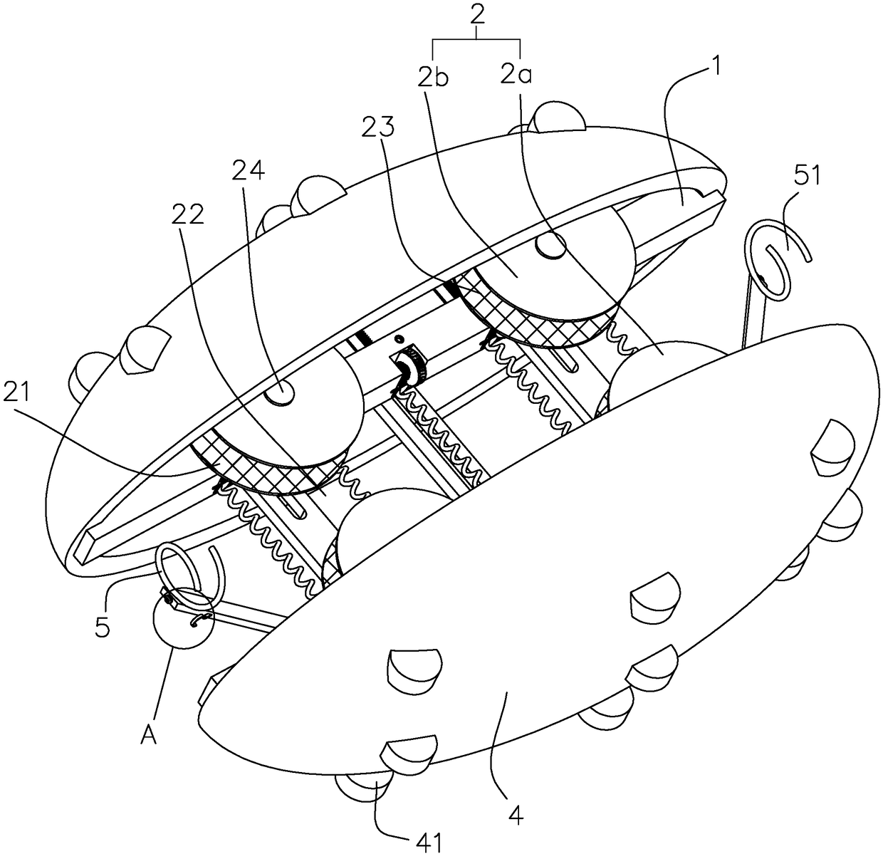
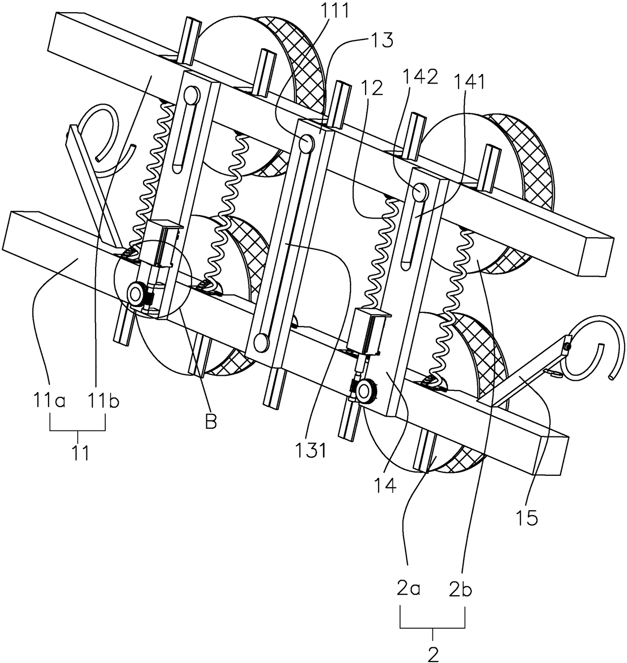
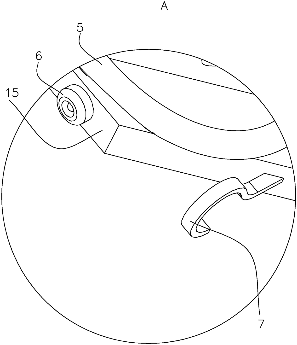
[0038] A communication pipeline pull line device, such as figure 1 and figure 2 , including a frame 1, the tail of the frame 1 is provided with a hook 7. The frame 1 includes two supporting rods 11 parallel to each other and a limiting rod 13 arranged between the two supporting rods 11 . Two pairs of rollers 2 are arranged near the four ends of the two support rods 11 , and the diameter of the rollers 2 is larger than the width of the support rods 11 . The optical cable can be passed between the two rollers 2, and a clamping groove 22 is formed between the rollers 2 to clamp the optical cable. The roller 2 rolls and moves in the pipeline along the direction of the optical cable.

[0039] Such as figure 1 , The outer ring of the roller 2 is provided with a concave clamping cavity 21, and the clamping cavity 21 is set as U-shaped to fit the outer wall of the optical cable. A clamping groove 22 for clamping the optical cable is formed between the two rollers 2 arranged in p...


PUM


Abstract

The invention relates to the field of communication line engineering, and discloses a communication pipe traction line device. The communication pipe traction line device comprises a rack; rollers arearranged on the rack; the rollers are arranged on the frame in pairs; a control motor for driving the rollers to rotate is arranged on the rack; at least one pair of rollers are rotatably connected to the rack; recessed line clamping cavities are arranged in outer rings of the rollers; a line clamping groove for clamping an optical cable is formed by the line clamping cavities and between the tworollers arranged in pairs; and a hook for hooking a traction line is arranged on an end of the rack. The rollers and the line clamping grooves are arranged such that the rack uses the original optical cable as a guiding rail and moves in a pipe so as to ensure that a traction line is parallel to the optical cable; advancing and retreating can be controlled by the control motor, manual operationsare reduced, the penetrating effect of the traction line is improved, and the communication pipe traction line device is easy to use.

Description

technical field [0001] The invention relates to the field of communication line engineering, in particular to a communication pipeline pulling line device. Background technique [0002] At present, in communication engineering, optical cable laying is an important part of communication system construction. [0003] At present, the Chinese patent with the publication number CN107086502A discloses a communication pipeline lead wire arrangement device, which includes a fuselage, an arc guide block arranged at one end of the fuselage, a motor arranged at the end of the fuselage away from the arc guide block, and a The impeller on the rotating shaft of the motor is used to push the fuselage forward, and the optical cable lead is set on the motor to pull the optical cable; the fuselage is cylindrical, and the arc guide block, the fuselage, and the motor are coaxially arranged, and the arc guide block The end away from the arc is connected to the fuselage in rotation, and the end ...

Claims


Application Information

Patent Timeline
Patent Type & Authority Applications(China)
IPC IPC(8): H02G1/08
CPCH02G1/088G02B6/54
Inventor 张枫华张朱晨
Owner NANJING LONGMA COMM ENG CO LTD
Why Eureka
Try Eureka