Switch cabinet and cabinet body thereof

A switch cabinet and cabinet body technology, which is applied in the direction of casing/cabinet/drawer components, electrical equipment casing/cabinet/drawer, electrical components, etc., can solve the problems of poor waterproof and dustproof ability of switch cabinets, and achieve improvement Waterproof and dustproof ability, reduced knock intensity, high structural strength effect

Pending Publication Date: 2018-09-25
HENAN SENYUAN ELECTRIC CO LTD
View PDF10 Cites 0 Cited by
  • Summary
  • Abstract
  • Description
  • Claims
  • Application Information

AI Technical Summary

Problems solved by technology

[0004] The purpose of the present invention is to provide a switchgear cabinet, which can solve the problem of poor waterproof and dustproof ability of the switchgear in the prior art. In addition, the purpose of the present invention is to provide a switchgear using the switchgear , improve the waterproof and dustproof ability of the switchgear, and ensure the working safety of the switchgear

Method used


Image

  • Switch cabinet and cabinet body thereof
  • Switch cabinet and cabinet body thereof
  • Switch cabinet and cabinet body thereof

Examples


Embodiment 1

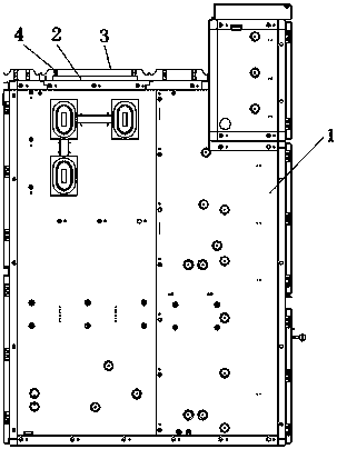
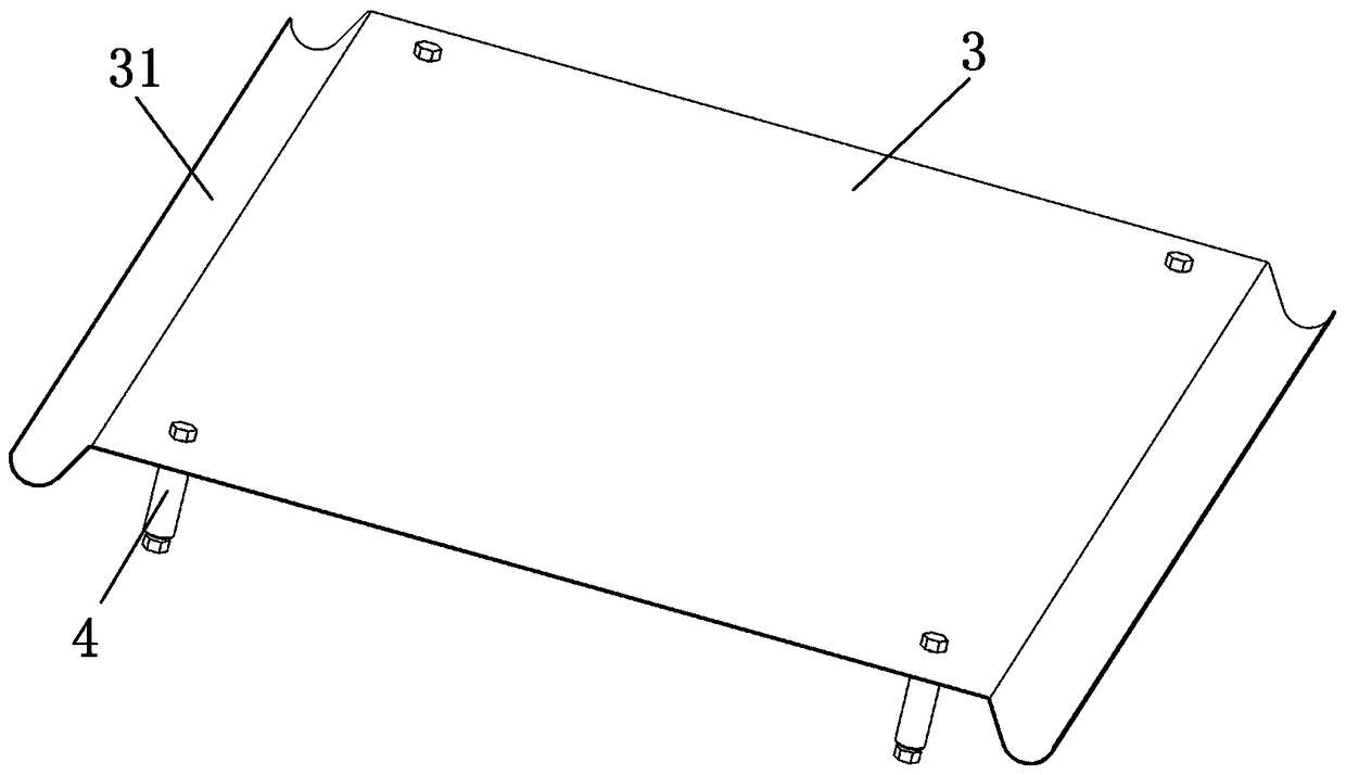
[0050] Such as Figure 1 to Figure 4As shown, it is Embodiment 1 of the switchgear in the present invention: the switchgear 1 includes a cabinet body and electrical components arranged in the cabinet body, the top of the cabinet body is provided with a pressure relief port, and the pressure relief port is equipped with a The pressure relief plate 2 for blocking the mouth is provided with a pressure relief hole for the gas to flow out from the cabinet body on the pressure relief plate 2. In order to prevent water or dust from entering the switch cabinet 1 from the pressure relief hole, a protective cover 3 is also arranged on the pressure relief plate 2, and the protective cover 3 is arranged above the pressure relief plate 2 and the pressure relief hole. There is also an interval between the pressure plates 2. When a short-circuit accident occurs in the switch cabinet 1, part of the high-temperature and high-pressure gas generated by the accident will first flow out from the p...

Embodiment 2

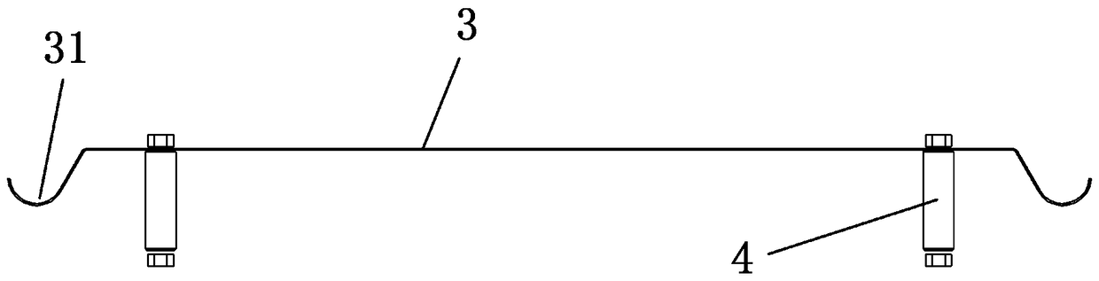
[0057] Such as Figure 5 As shown, it is Embodiment 2 of the switchgear in the present invention: the difference from the above-mentioned embodiments is only in the structure of the protective cover. The protective cover 3 is still formed by bending a rectangular bottom plate, but the diversion groove 31 is arranged on the On the long side of the rectangular bottom plate, it can be applied to switch cabinets of different sizes.

[0058] In other embodiments, the structure of the protective cover can also be replaced with other forms, for example, only the rectangular bottom plate is provided with a folded edge that is folded toward the side of the cabinet body, and water can fall from the folded edge.

[0059] In other embodiments, the structure of the protective cover can also be replaced with other forms, for example, the entire protective cover is set as a slope or arc structure, and when water falls on the protective cover, it will fall from the protective cover.

[0060]...


PUM


Abstract

The invention provides a switch cabinet and a cabinet body thereof. The switch cabinet comprises a cabinet body and an electrical component disposed in the cabinet body; the cabinet body comprises a pressure relief port formed in the cabinet body and pressure relief plates covering the pressure relief port; protective covers are arranged on the top of the cabinet body and above the pressure reliefplates; the protective covers are correspondingly fixed on the pressure relief plates to move together with the pressure relief plates. The pressure relief plates are provided with the protective covers, and the protective covers are located above the pressure relief plates. When external dust or water is allowed to enter the switch cabinet through the cooperation between the pressure relief plates and the pressure relief port, the protective covers can achieve a waterproof and dustproof effect on pressure relief holes. The protective covers are fixed on the pressure relief plates. When the pressure relief plates are bounced by the high-temperature high-pressure gas, the protective covers will move together with the pressure relief plates, and the protective covers will not interfere withthe action of the pressure relief plates, the waterproof and dustproof capacity of the cabinet body is improved, and the use safety of the switch cabinet is ensured.

Description

technical field [0001] The invention relates to a switch cabinet and its cabinet body. Background technique [0002] There are a large number of electrical components integrated in the switchgear. These components will cause short circuit faults due to short circuit, insulation aging or human error during operation. The short circuit current of tens of thousands of amperes will instantly generate high temperature and high pressure gas in the cabinet. If These gases cannot be released in a short time and will damage the switchgear. In the prior art, the top of the switchgear is provided with a pressure relief port, and the pressure relief port is fitted with a pressure relief plate, which springs up after being impacted by the air pressure of the cabinet to release the gas in the cabinet. [0003] However, in the prior art, due to the limitation of matching accuracy, there is a small gap between the pressure relief plates and the pressure relief port, and the dust or water i...

Claims


Application Information

Patent Timeline
Patent Type & Authority Applications(China)
IPC IPC(8): H05K5/02
CPCH05K5/0217H05K5/03
Inventor 商建超崔晓科赵楠
Owner HENAN SENYUAN ELECTRIC CO LTD
Why Eureka
Try Eureka