LED assembly with vented circuit board

a technology of vented circuit boards and led assemblies, applied in the field of lighting units, can solve the problems that the display assemblies used in outdoor environments may be exposed to wind forces affecting the load of the assembly, and achieve the effect of promoting cooling and reducing wind resistan

Inactive Publication Date: 2006-11-21
ILLUMAFINITY LLC +1
View PDF46 Cites 39 Cited by
  • Summary
  • Abstract
  • Description
  • Claims
  • Application Information

AI Technical Summary

Benefits of technology

[0003]In one variation, a printed circuit board assembly includes a plurality of LEDs disposed in a grid pattern at junctions in which the junctions are interconnected by adjacent bridges defining air vents. A plurality of vents enables air to pass through the printed circuit board assembly, thus reducing wind resistance and promoting cooling.
[0006]In yet another variation, a printed circuit board assembly includes a plurality of LEDs having a dome. The LEDs may be disposed in a grid pattern at junctions being interconnected by bridges defining air vents. The bridges include a substrate for activating the LEDs and the substrate includes a front side including the LEDs and an opposing a rear side. Aerodynamic members configured to reduce air pressure are disposed on the second side of the substrate corresponding to location of the junctions. In this way, wind loading may be reduced for multiple directions. Other variations are described in more detail herein.

Problems solved by technology

Furthermore, display assemblies when used in outdoor environments may be exposed to wind forces that affect loading on the assemblies.

Method used


Image

  • LED assembly with vented circuit board
  • LED assembly with vented circuit board
  • LED assembly with vented circuit board

Examples


Embodiment Construction

[0026]In the following description of the various embodiments, reference is made to the accompanying drawings, which form a part hereof, and in which is shown by way of illustration various embodiments in which the invention may be practiced. It is to be understood that other embodiments may be utilized and structural and functional modifications may be made without departing from the scope of the present invention.

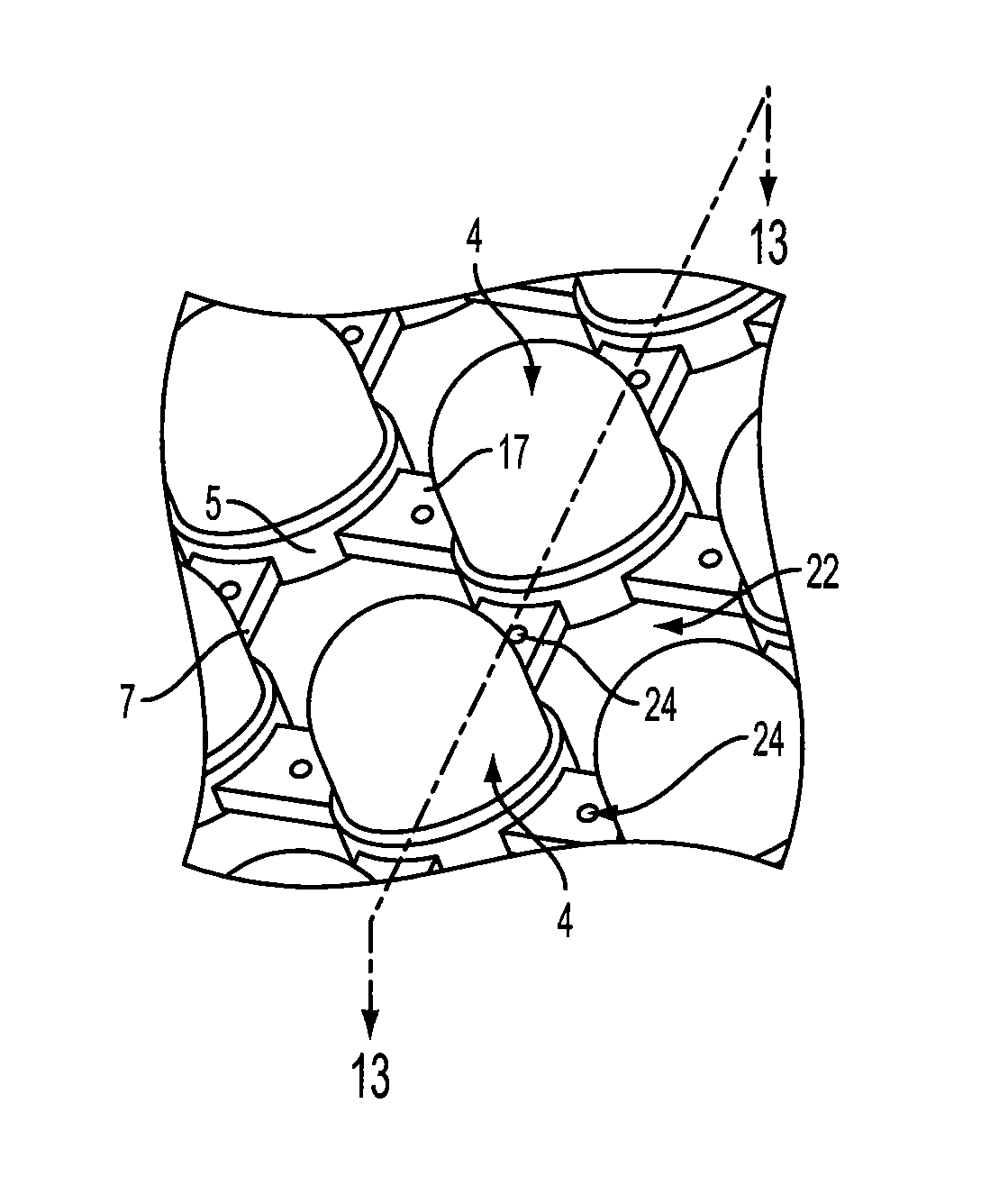
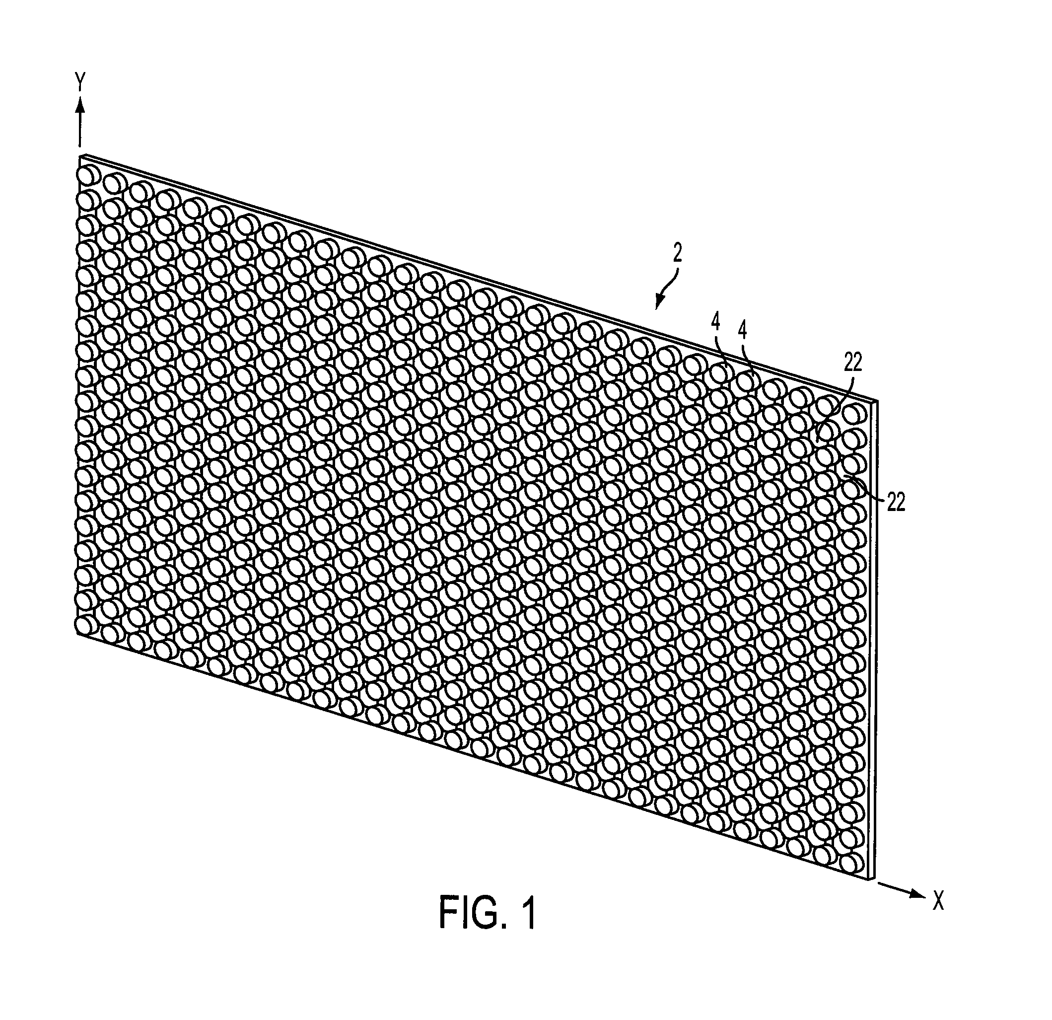
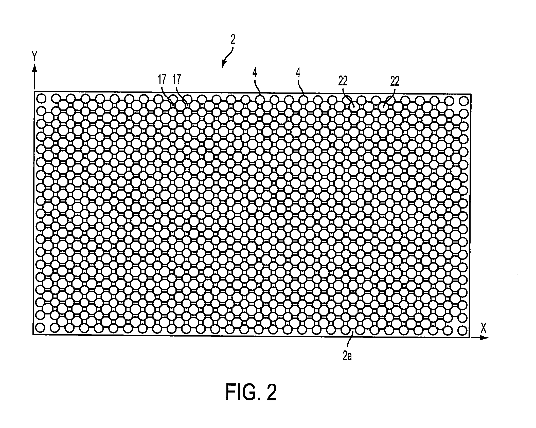
[0027]FIGS. 1–4 illustrate an embodiment of a printed circuit board (PCB) assembly 2 including an array or grid pattern of light emitting diode (LED) modules 4 mounted thereon. In one arrangement, the LED modules 4 are disposed at intersecting junctions 5 of the PCB assembly 2 in a generally perpendicular X-direction and Y-direction based on a Cartesian coordinate system. The junctions 5 (see FIG. 3) are interconnected by a plurality of bridges 17 defining vents 22, which may be drilled or routed in the printed circuit board. While the terminology “printed circuit board” ...


PUM


Abstract

A light emitting diode (LED) assembly with a vented printed circuit board is disclosed. A printed circuit board assembly may include a plurality of LED modules disposed in an array with a multilayered substrate and a plurality of vents. The multilayer substrate may include a thermal cooling layer which is in thermal communication with the LED modules for heat dissipation. The multilayer substrate may include one or more electrical power layers in electrical communication with the LED modules for energizing the LEDs. The multilayered substrate may have an external insulating layer that includes a plurality of fluid apertures configured for fluid communication with the thermal cooling layer.

Description

FIELD OF THE INVENTION[0001]The invention relates to lighting units using light emitting diodes (LEDs). More particularly, the invention relates to a light emitting diode assembly with a vented circuit board.BACKGROUND OF THE INVENTION[0002]Light-emitting diodes (LEDS) have been used for signs and other types of illuminated displays for many years. As a byproduct of operation, display assemblies having LEDs generate heat as electric current flows through the devices. The heat must be dissipated or removed to prevent overheating. Cooling a display assembly is important in order to preserve its functionality and efficiency. Furthermore, display assemblies when used in outdoor environments may be exposed to wind forces that affect loading on the assemblies. One approach for cooling an LED display assembly is shown in PCT publication WO2004019657. The publication generally shows a coolant fluid which cools LEDs using a mesh design.BRIEF SUMMARY OF THE INVENTION[0003]In one variation, a ...

Claims


Application Information

Patent Timeline
Patent Type & Authority Patents(United States)
IPC IPC(8): H01L29/00G09F9/33G09F13/20H05K1/02H05K3/28
CPCG09F9/33G09F13/20H05K1/0209H05K3/28H05K2201/064H05K2201/0989H05K2201/10106H05K2201/1056H05K2203/081H05K2203/1178
Inventor RAOS, ROBERT BOGDANDESAI, NILESH THAKORFLANK, STEVEN
Owner ILLUMAFINITY LLC
Why Eureka
Try Eureka