Liquid cooling type heat-dissipating device

a heat dissipating device and liquid cooling technology, which is applied in the direction of liquid fuel engines, lighting and heating apparatus, machines/engines, etc., can solve the problems of increasing power consumption, reduce the cooling effect of heat dissipating fans, reduce heat dissipating area, and reduce heat dissipation area

Inactive Publication Date: 2008-07-10
INVENTEC CORP
View PDF3 Cites 27 Cited by
  • Summary
  • Abstract
  • Description
  • Claims
  • Application Information

AI Technical Summary

Benefits of technology

[0008]According to the conventional art disclosed above, the heat-dissipating area is reduced due to an inadequate storage space of a pipe, and the cooling effect of the heat-dissipating fan is red

Problems solved by technology

In this manner, the arrangement of two motor increases the number of the components required and the overall assembly volume of the liquid coo

Method used


Image

  • Liquid cooling type heat-dissipating device
  • Liquid cooling type heat-dissipating device
  • Liquid cooling type heat-dissipating device

Examples


first embodiment

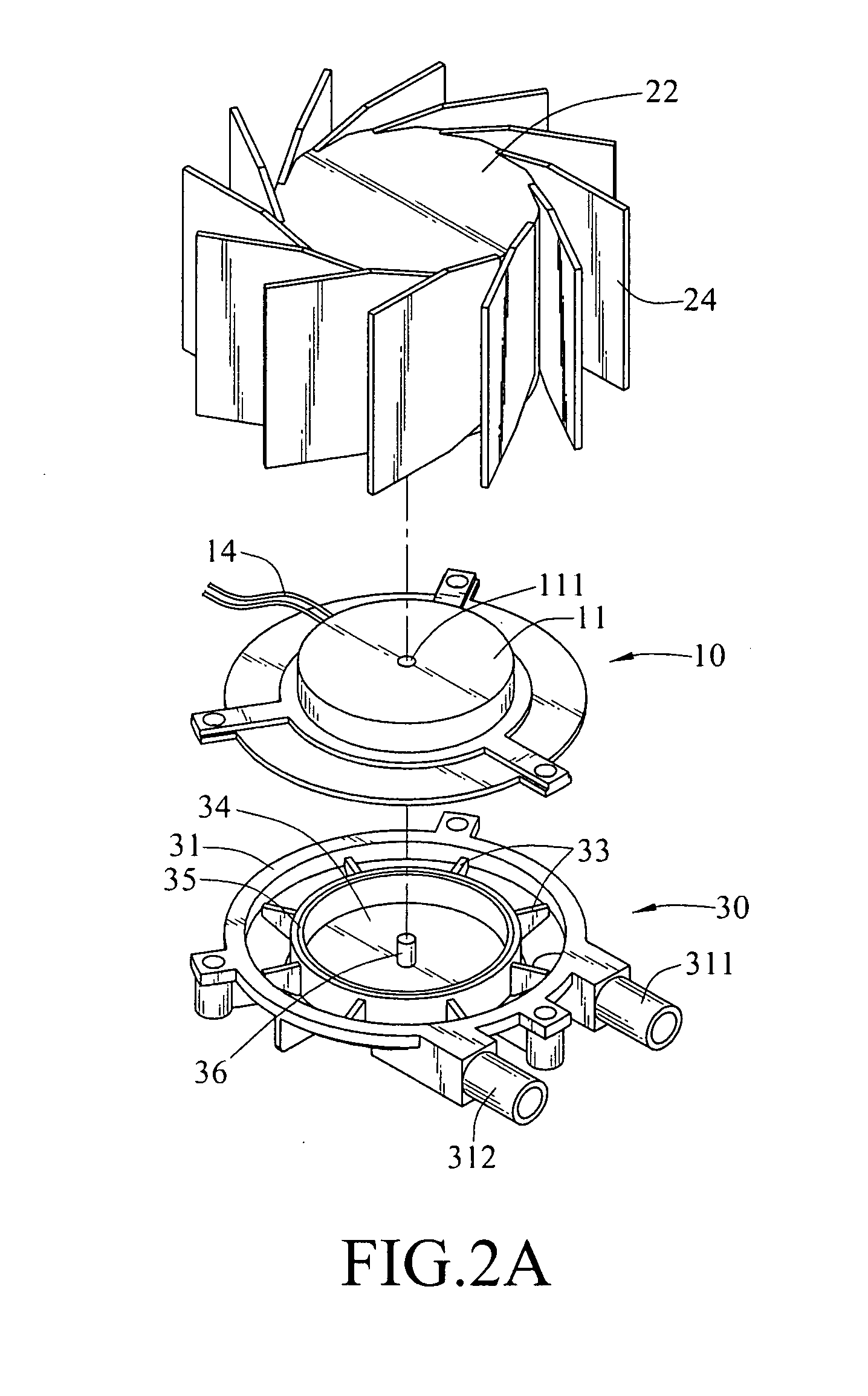
[0024]Referring again to FIGS. 2A, 2B, 3, 4, and 5, in the liquid cooling type heat-dissipating device of the present invention, as being assembled, the shaft pin 36 of the chamber 34 is received in the shaft hole 121 of the second stator 12. In this way, the second stator 12 of the motor 10 is accommodated by the chamber 34 of the pump 30, such that the second stator 12 and the second magnetic element 35 within the chamber 34 may induct each other so as to drive the turbine 33 to rotate. Additionally, the shaft pin 26 of the fan hub 22 is received in the shaft hole 111 of the first stator 11, such that the first stator 11 of the motor 10 is accommodated within the fan hub 22, and thus the first stator 11 of the motor 10 and the first magnetic element 25 within the fan hub 22 may induct each other so as to drive the fan blade 24 to rotate.

[0025]After the first stator 11 and the second stator 12 of the motor 10 is powered through the power supply wire 14, the first stator 11 and the ...

second embodiment

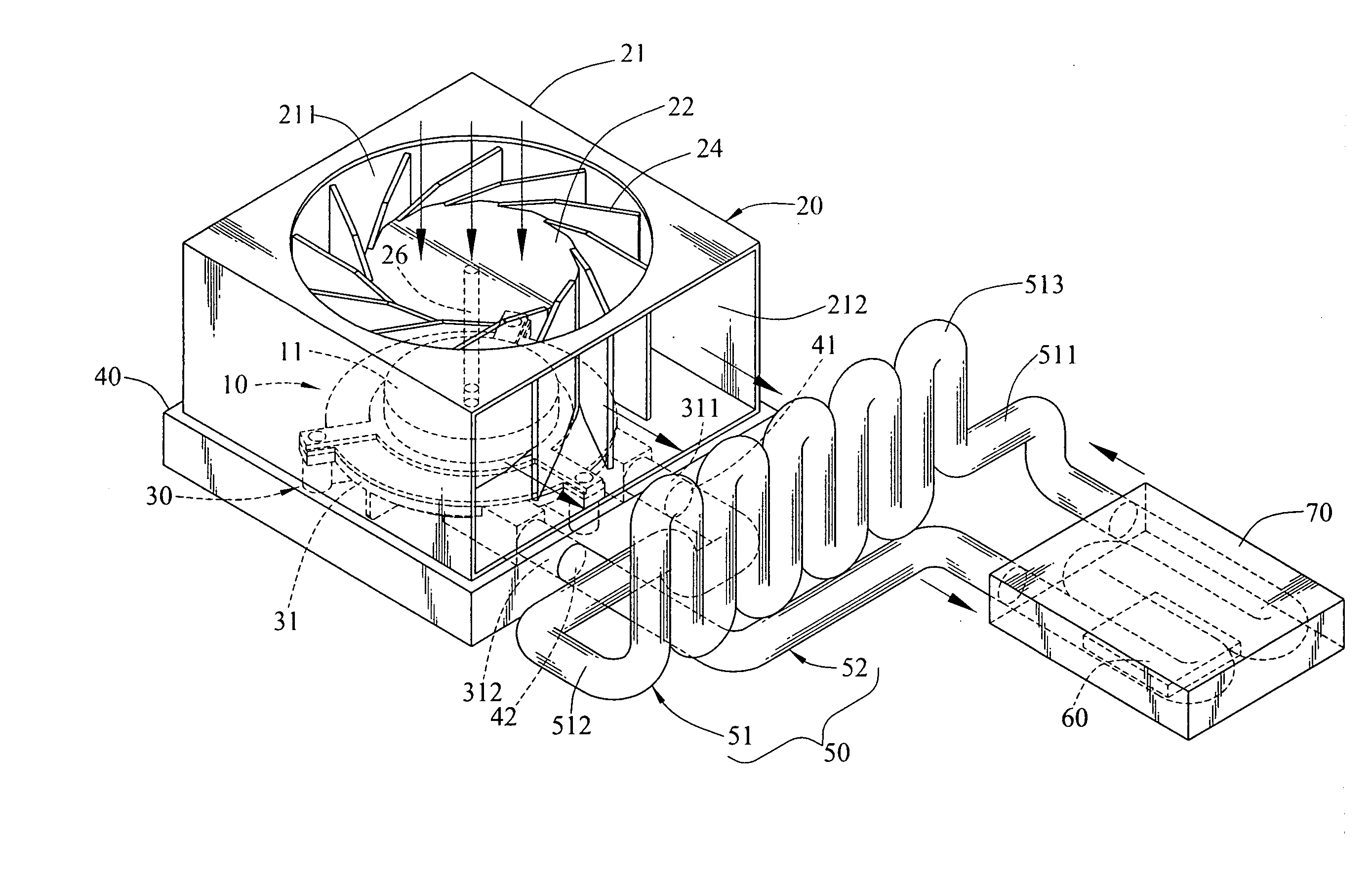
[0028]Referring to FIG. 6, a schematic view of a forward wind blow of a second embodiment to the liquid cooling type heat-dissipating device according to the present invention is shown. Since the curved portion 513 in the liquid entrance section 51 has a large heat dissipation area, and a position corresponding to the radial wind outlet 212 is blown by the heat-dissipating fan 20, the curved portion 513 is used as a temperature dropping section for the working liquid, therefore, when the curved portion 513 of the liquid entrance section 51 is further connected to a heat exchanger 80, the working liquid within the liquid entrance section 51 may be cooled more quickly and thus more heat may be dissipated.

third embodiment

[0029]Moreover, the above-mentioned motor 10 rotates the fan blade 24 and the blades 33 coaxially and at the same speed. However, the motor 10 may also rotate the fan blade 24 and the blades 33 uncoaxially and at different revolving speeds, and thus a third embodiment is disclosed in the present invention.

[0030]Referring to FIGS. 7A and 7B, in order to make the motor 10, the fan hub 22 and the turbine 33 be located in different axis positions, a central shaft 16 having two ends projected from the end surfaces of the first stator 11 and the second stator 12 is disposed in the motor 10, and eccentric shafts 17, 18 are respectively disposed on the end surfaces of the first stator 11 and the second stator 12, adjacent to the central shaft 16. Additionally, a first gear set 90 and a second gear set 90′ with different reduction gear ratios are respectively disposed between the motor 10 and the fan hub 22 and between the motor 10 and the turbine 33. In this way, when the motor respectively...


PUM


Abstract

A liquid cooling type heat-dissipating device for exchanging heat with a heat source is provided, which includes a heat-dissipating fan, a pump, a liquid pipe, a motor, and a heat-dissipating block. The motor drives the heat-dissipating fan and the pump. Two ends of the liquid pipe are connected to the pump so as to form a fluid loop, wherein the liquid pipe is in contact with the heat-dissipating block, and the heat-dissipating block is disposed on the heat source. The liquid pipe is continuously curved on a segment away from the heat-dissipating block to form a curved portion located on a wind output path of the heat-dissipating fan, therefore, the heat-dissipating fan cools the curved portion by blowing wind, so as to increase the speed of temperature dropping thereby improving the heat dissipation performance of the liquid pipe.

Description

BACKGROUND OF THE INVENTION[0001]1. Field of Invention[0002]The present invention relates to a liquid cooling type heat-dissipating device, and more particularly to a heat-dissipating device that can improve the cooling capability of a liquid pipe.[0003]2. Related Art[0004]Electronic elements such as a central processing unit (CPU) and a power integrated circuit (IC) in the computer generate heat when performing operation and a working temperature is also increased as the operation process goes on. Because the working temperature has a significant effect on whether a breakdown occurs to the computer equipment, in order to reduce the working temperature of the electronic elements that generate heat and keep the electronic elements well function, a variety of heat-dissipating devices have been introduced, one of which is, for example, a liquid cooling type heat-dissipating device. The liquid cooling type heat-dissipating device includes a heat sink, a coolant cycling apparatus and a f...

Claims


Application Information

Patent Timeline
IPC IPC(8): H05K7/20
CPCF04D13/12F04D25/163F04D29/586H01L23/473H01L2924/0002H01L2924/00
Inventor CHEN, WEN-HUA
Owner INVENTEC CORP
Why Eureka
Try Eureka