
External mix air atomizing spray nozzle assembly

a technology of atomizing spray nozzle and external mix, which is applied in the direction of electrostatic spraying apparatus, burners, lighting and heating apparatus, etc., can solve the problems of ineffectiveness, insufficient pressurized air supply generated by low-pressure blowers, and further pressure losses that detract from efficient spray nozzle operation, etc., to achieve more efficient and reliable operation

Inactive Publication Date: 2006-02-14
SPRAYING SYST
View PDF14 Cites 40 Cited by
  • Summary
  • Abstract
  • Description
  • Claims
  • Application Information

AI Technical Summary

Benefits of technology

[0003]It is an object of the present invention to provide an external mix air atomizing spray nozzle assembly which is adapted for more efficient and reliable operation.
[0004]Another object is to provide an external mix air atomizing spray nozzle assembly as characterized above which can be effectively operated at substantially lower air pressures than heretofore possible.
[0005]A further object is to provide an external mix spray nozzle assembly of the above kind which can be effectively operated at relatively low air pressures in producing flat or full cone liquid spray patterns with substantially uniform liquid particle breakdown.
[0006]Still another object is to provide such an external mix air atomizing spray nozzle assembly that has an air-directing cap which is adapted for more economical manufacture. A related object is to provide a reliable method of making such air cap.

Problems solved by technology

However, such spray nozzles typically must be formed with intricate air flow passages which communicate through the spray nozzle to locations downstream of the liquid discharge orifice.
Such passageways are expensive to manufacture, create pressure losses, and if not formed with precision and accuracy can result in burrs and passage misalignments that cause further pressure losses that detract from efficient operation of the spray nozzle.
Hence, the pressurized air supply generated by low-pressure blowers sometimes is inadequate to enable effective liquid particle breakdown and direction.
Moreover, while external mix air atomizing spray nozzles have been used for producing flat fan spray patterns, heretofore they have not been effective, at low pressures, for generating full cone liquid spray patterns with substantially uniform liquid particle breakdown.

Method used


Image

  • External mix air atomizing spray nozzle assembly
  • External mix air atomizing spray nozzle assembly
  • External mix air atomizing spray nozzle assembly

Examples


Embodiment Construction

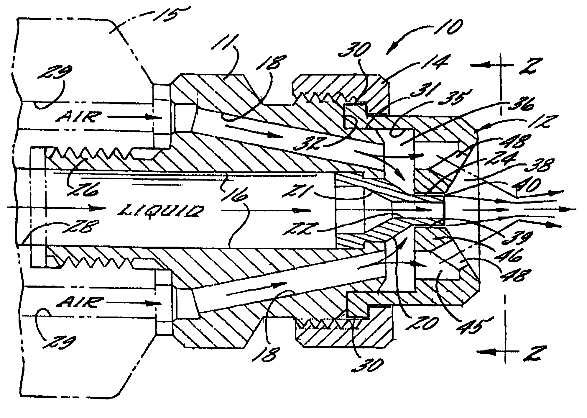
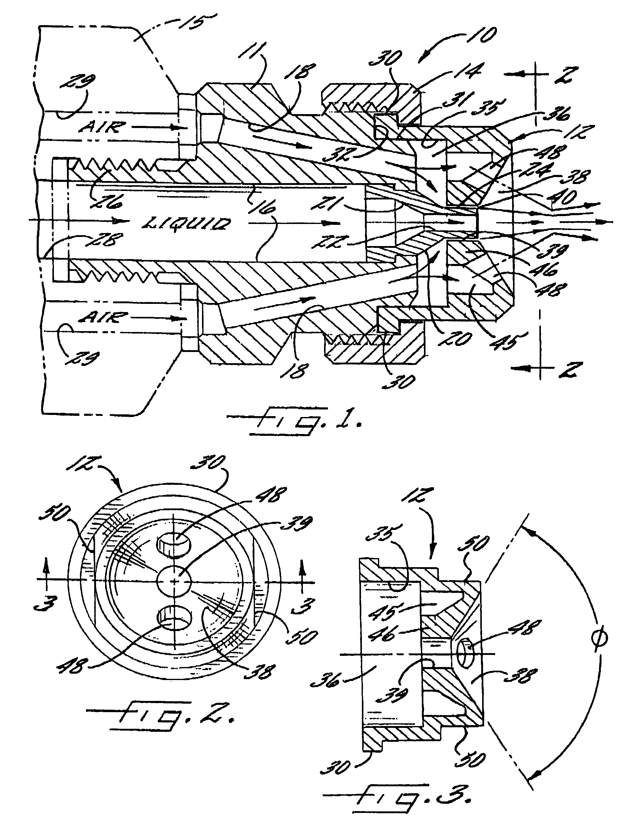
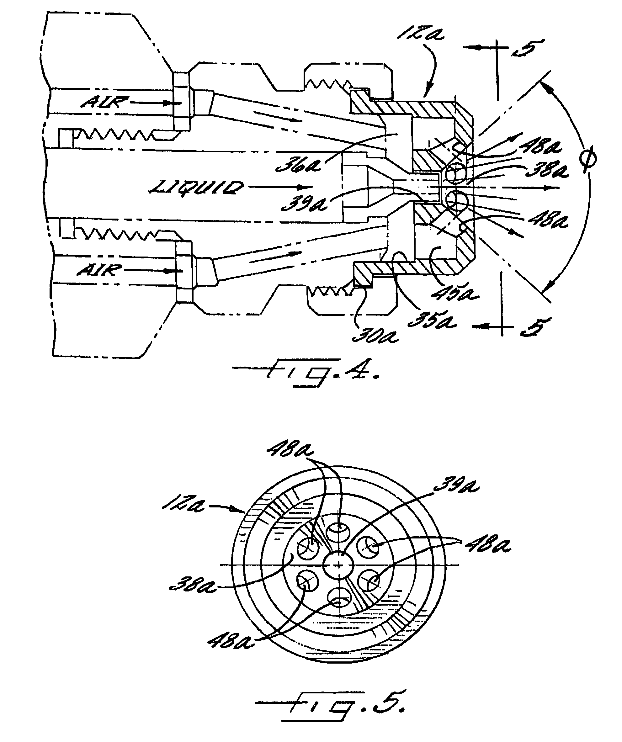
[0018]Referring now more particularly to the drawings, there is shown an illustrative spray nozzle assembly 10 embodying the present invention. The spray nozzle assembly 10 in this case comprises a nozzle body 11, an air cap 12 mounted at the downstream into the nozzle body 11, and a retaining ring 14 for releasably securing the air cap 12 in mounting position. The illustrated spray nozzle assembly 10 is mounted on a base portion15 through which pressurized liquid and air is supplied from appropriate sources.

[0019]The illustrated nozzle body 11 is formed with a central liquid passage 16 and a plurality of pressurized air or gas passages 18 disposed in circumferentially spaced relation about the liquid passage 16. The liquid passage 16 in this case communicates with a liquid discharge spray tip 20 fixed in the downstream end of the nozzle body 11 in forwardly extending relation thereto. The liquid spray tip 20 defines a tapered entry chamber 21 which communicates with a smaller diame...


PUM


Abstract

An external mix air assisted spray nozzle assembly having a nozzle body, and an air cap for a directing pressurized air streams on a discharging liquid stream external to the liquid discharge orifice of the nozzle assembly for atomizing and forming the liquid into the desired spray pattern. The air cap includes an upstream internal air chamber, an external, downstream liquid discharge and mixing chamber, and a central opening coaxial with the liquid discharge orifice communicating between the upstream and downstream chambers. The air cap further includes a plurality of angled pressurized air discharge passages which communicate with an annular plenum of the air chamber disposed in surrounding relation to the central opening for enabling substantially uniform particle breakdown and distribution at lower air pressures than heretofore possible.

Description

[0001]The present invention relates generally to spray nozzle assemblies, and more particularly, to “external mix” air atomizing spray nozzle assemblies in which a discharging liquid flow stream is atomized and formed into the desired spray pattern by pressurized air externally of the liquid discharge orifice.BACKGROUND OF THE INVENTION[0002]External mix air atomizing spray nozzles are known for their ability to control of liquid particle size and spray distribution by pressurized air, independent of the liquid flow rate. They also can be used with relatively low pressure air supplies, such as on the order of 15 psi, which can be generated from inexpensive blowers, rather than air compressors. However, such spray nozzles typically must be formed with intricate air flow passages which communicate through the spray nozzle to locations downstream of the liquid discharge orifice. Such passageways are expensive to manufacture, create pressure losses, and if not formed with precision and ...

Claims


Application Information

Patent Timeline
IPC IPC(8): B05B5/00A62C5/02B05B1/28B05B7/06B05B7/08B05B7/10
CPCB05B7/10B05B7/0861B05B7/066B05B7/0815
Inventor HARUCH, JAMES
Owner SPRAYING SYST
Learn More