A continuous metal mold split-type bending structure and bending forming method thereof

A metal mold, split-type technology, applied in the direction of forming tools, metal processing equipment, manufacturing tools, etc., can solve the problems of flatness of the bottom surface of the side wall outreach, affecting the quality of assembled products, and insufficient, so as to reduce the auxiliary workload and save The effect of manpower and material resources and convenient adjustment

Active Publication Date: 2022-01-14
NINGBO BEILONG PRECISION MOLDING
View PDF8 Cites 0 Cited by
  • Summary
  • Abstract
  • Description
  • Claims
  • Application Information

AI Technical Summary

Problems solved by technology

[0003] The present invention mainly provides a continuous metal mold split-type bending structure and its bending forming method which can adjust and ensure the verticality and flatness of the U-shaped metal stamping formed parts corner verticality and flatness with simple structure and ingenious conception. The U-shaped products in the technology are prone to side wall outreach and insufficient flatness of the bottom surface, which directly affect the quality of assembled products and other technical problems

Method used


Image

  • A continuous metal mold split-type bending structure and bending forming method thereof

Examples


Embodiment 1

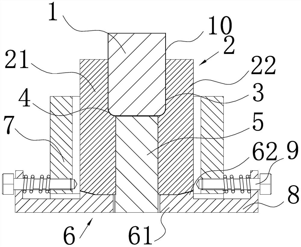
[0023] Such as figure 1 As shown, a continuous metal mold split-type bending structure of the present invention includes a forming bending die 2 composed of a left lifting die 21 and a right lifting die 22, a left lifting die 21 and a right lifting die 22 It is distributed symmetrically on the left and right, and the lower ends of the two clamp the lifting pusher block 5, and the upper ends of the left lifter die 21, the right lifter die 22 and the lifter pusher block 5 jointly enclose the synthetic molding cavity 3, and the lifter pusher The inner surfaces of the left lifting die 21 and the right lifting die 22 corresponding to the two sides of the material block 5 respectively form a straight line forming fillet 4, and the inner surfaces of the left lifting die 21 and the right lifting die 22 are formed by the linear forming fillet 4 and the inner surface of the right lifting die 22 respectively. The two ends of the top surface of the lifting pusher block 5 form a fillet tra...

Embodiment 2

[0034] The adjusting screw rod 9 is screwed horizontally on the longitudinal edge of the L-shaped tie rod 8, and the screw-in end of the adjusting screw rod 9 is abutted on the outer surface of the lower formwork 7.


PUM


Abstract

The invention relates to a metal mold split bending structure, which provides a continuous metal mold split bending structure with simple structure, ingenious concept, which can adjust and ensure the verticality and flatness of the U-shaped metal stamping forming parts corner verticality and flatness. The bending forming method solves the technical problems that the U-shaped products in the prior art are prone to side wall outreach and the flatness of the bottom surface is not enough, which directly affects the quality of assembled products. It includes forming bending dies and a fillet forming punch inserted into the forming bending die, the forming bending die includes a left lifting die and a right lifting die, and the upper ends of the left lifting die and the right lifting die are jointly formed Forming cavity, at the corners of the bottom of the forming cavity corresponding to the left lifting die and the right lifting die, there are respectively provided with straight line forming fillets that match with the fillet forming punch, and the corresponding left lifting die and right lifting die below the forming cavity A lift pushing block is sandwiched between the dies.

Description

technical field [0001] The invention relates to a metal mold split bending structure, in particular to a continuous metal mold split bending structure with simple structure, ingenious concept, which can adjust and ensure the verticality and flatness of the U-shaped metal stamping forming parts corner verticality and flatness. Bending method. Background technique [0002] Metal stamping parts are widely used in various fields, including high-end electronic products, such as electronic devices, smart phone accessories, auto parts, etc. Among them, stamping parts play an important role, and their quality directly affects the quality of assembled products. Metal stamping parts usually rely on presses and molds to exert external force on the profile, so that the material is deformed or separated, and the stamping product of the required shape and size is obtained, that is, formed by stamping, stretching and shearing, so the mold The structure and processing technology directly d...

Claims


Application Information

Patent Timeline
Patent Type & Authority Patents(China)
IPC IPC(8): B21D37/10B21D37/04B21D5/01
CPCB21D5/01B21D37/04B21D37/10
Inventor 诸文君
Owner NINGBO BEILONG PRECISION MOLDING
Why Eureka
Try Eureka