
a bending mold

A bending die and concave die technology, applied in the field of bending die, to achieve the effect of reducing cost, reducing overall weight, convenient and quick installation and disassembly

Active Publication Date: 2020-09-01
杨晓东 +1
View PDF11 Cites 0 Cited by
  • Summary
  • Abstract
  • Description
  • Claims
  • Application Information

AI Technical Summary

Problems solved by technology

[0004] In view of this, the object of the present invention is to provide a bending die for one-time forming, which aims to overcome the defect that the workpiece needs to be debugged and corrected many times due to the springback of the bent part when the traditional bending die is processed

Method used


Image

  • a bending mold
  • a bending mold

Examples


Embodiment Construction

[0024] It should be noted that, in the case of no conflict, the embodiments in the present application and the features in the embodiments can be combined with each other. The present invention will be described in detail below with reference to the accompanying drawings and examples.

[0025] In order to enable those skilled in the art to better understand the solution of the present application, the technical solution in the embodiment of the application will be clearly and completely described below in conjunction with the accompanying drawings in the embodiment of the application. Obviously, the described embodiment is only It is an embodiment of a part of the application, but not all of the embodiments. Based on the embodiments in this application, all other embodiments obtained by persons of ordinary skill in the art without creative efforts shall fall within the scope of protection of this application.

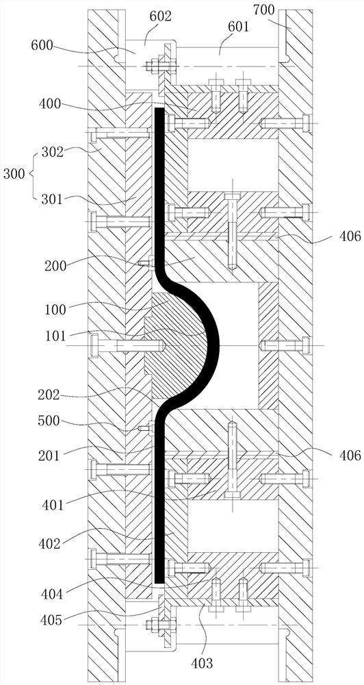
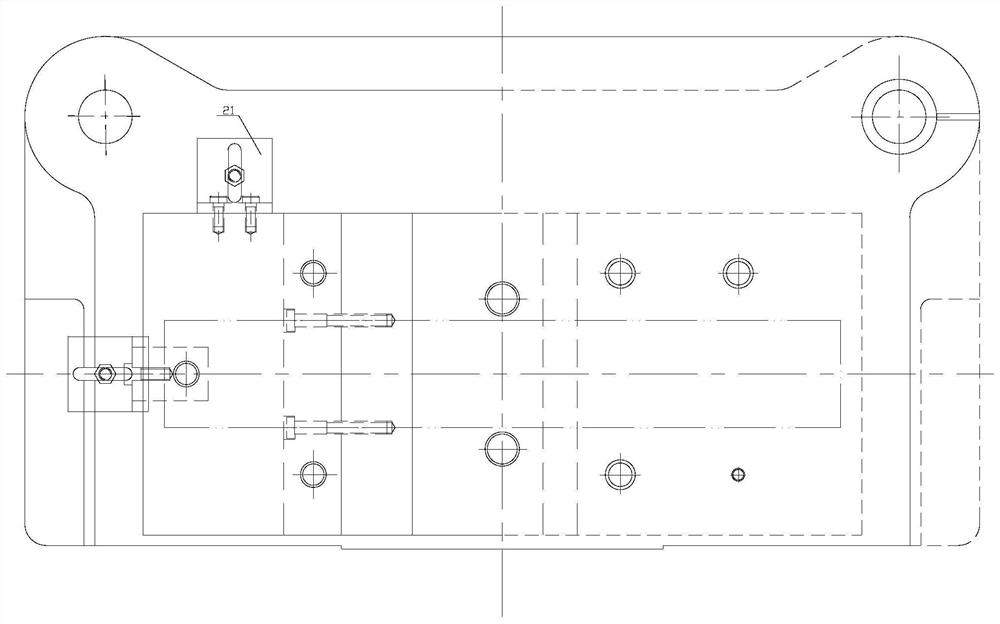
[0026] Such as Figure 1-2 As shown, a bending die includes: a p...


PUM


Abstract

The invention relates to a bending die. The bending die comprises a convex die, concave dies which are correspondingly distributed at two sides of the convex die, a convex die fixing device, combinedconcave die fixing devices, a spring-back stopping element and a guide device. According to the bending die, the spring-back stopping element is used for controlling the spring-back angle of a workingworkpiece after forming, and the spring-back stopping element is positioned right above a positon where a horizontal working part of each concave die is in transition connection with a second circular arc working part, and thus the bending workpiece can be formed in one time, and as a result, the defect of modifying and debugging the bending workpiece in a plurality of times after forming can beavoided; an adjusting gasket is arranged between each concave die and the corresponding combined concave die fixing device, and thus the bending part can be formed by different forming angles withoutintegrally replacing the die, and as a result, the cost is decreased, and an existing die is utilized to the maximum; the combined concave die fixing devices are adopted, so that the overall weight ofthe die is decreased, and moreover, the die is conveniently and quickly mounted and dismounted.

Description

technical field [0001] The invention belongs to the field of metal forming and processing, and relates to a novel mold structure for processing bent parts and similar parts, more specifically, to a bending die. Background technique [0002] Bending parts are one of the most numerous stamping parts in the manufacture of modern industrial products, automobiles, appliances, instruments and tools. Most of the bending parts are processed by bending dies. The existing bending dies include steel punches and dies. The punches are driven downward by the press, and the workpiece is bent under the joint action of the punches and dies. Forming, when using a bending die for bending forming, elastic-plastic deformation occurs in the fillet area of ​​the bending part, and after the bending part leaves the bending die, the elastic deformation recovers, causing the bending part to spring back. [0003] "Handbook of Practical Stamping Technology" (TG38-62, Beijing; Mechanical Industry Press,...

Claims


Application Information

Patent Timeline
Patent Type & Authority Patents(China)
IPC IPC(8): B21D37/10
CPCB21D37/10
Inventor 杨晓东王兴廖焰常志梁王全聪
Owner 杨晓东
Learn More