Vehicle A column invisible imaging structure

A polygonal structure, invisible technology, applied in vehicle parts, optical observation devices, transportation and packaging, etc., can solve the problems of more occlusion of the driver's field of view and large blind spots of the driver's angle of view, so as to increase the field of view and reduce the blind spot of the angle of view. , the effect of improving safety

Inactive Publication Date: 2018-09-28
SAIC MOTOR
View PDF5 Cites 1 Cited by
  • Summary
  • Abstract
  • Description
  • Claims
  • Application Information

AI Technical Summary

Problems solved by technology

[0002] The A-pillar is the connecting column connecting the roof and the front compartment of the left front and the right front. Between the engine compartment and the cockpit, above the left and right rearview mirrors, the vehicle A-pillar of the prior art is a completely opaque area, which is harmful to the driver. The driver's field of view is blocked more, especially when the vehicle is turning, the blocking of the vehicle's A-pillar leads to a larger blind spot of the driver's perspective

Method used


Image

  • Vehicle A column invisible imaging structure
  • Vehicle A column invisible imaging structure
  • Vehicle A column invisible imaging structure

Examples


Embodiment 1

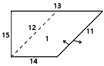
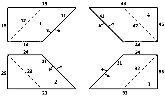
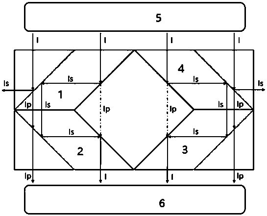
[0025] See attached figure 1 And attached figure 2 , A vehicle A-pillar invisible imaging structure, comprising a first invisible device 1, a second invisible device 2, a third invisible device 3 and a fourth invisible device 4, the first invisible device 1, the second invisible device 2, The third invisible device 3 and the fourth invisible device 4 are connected to each other in a polygonal structure and arranged symmetrically. The first invisible device 1, the second invisible device 2, the third invisible device 3 and the fourth invisible device 4 are distributed in central symmetry and axial symmetry. .

[0026] The first invisible device 1 includes a first P polarizer 11, a first S polarizer 12, a first transparent surface 13, a second transparent surface 14 and a third transparent surface 15. The first P polarizer 11, the first transparent surface The transparent surface 13, the third transparent surface 15 and the second transparent surface 14 are connected end to end to...


PUM


Abstract

The invention discloses a vehicle A column invisible imaging structure. The vehicle A column invisible imaging structure comprises a first invisible device (1), a second invisible device (2), a thirdinvisible device (3) and a fourth invisible device (4). The first invisible device, the second invisible device, the third invisible device and the fourth invisible device are connected to each otherin a polygonal structure mode and symmetrically arranged. The invisible devices each comprise a P polarizing film, an S polarizing film and three transparent surfaces, wherein the P polarizing film and the three transparent surfaces are connected end to end to form a quadrilateral structure, and the S polarizing film is arranged in the quadrilateral structure by forming a 45-degree included anglewith the transparent surfaces and arranged in parallel with the P polarizing film. An object (5) is located on the outer sides of the first invisible device and the fourth invisible device, and imaging (6) is located on the outer sides of the second invisible device and the third invisible device. The vehicle A column invisible imaging structure enlarges the visual field of drivers by using the propagation characteristic of light, effectively relieves the visual field blind area problem of the drivers, and improves the safety of vehicle driving.

Description

Technical field [0001] The invention relates to a vehicle structural component, in particular to a vehicle A-pillar hidden imaging structure. Background technique [0002] The A-pillar is a connecting column connecting the front left and front right of the car roof and the front cabin. Between the engine compartment and the cockpit, above the left and right rearview mirrors, the A-pillar of the prior art vehicle is a completely opaque area, which is not transparent for driving. The driver’s field of vision is more occluded, especially when the vehicle is turning, the occlusion of the A-pillar of the vehicle results in a larger blind area of ​​the driver’s perspective. [0003] The biggest effect of the A-pillar on the car is to improve the stiffness of the body, in order to enhance the passive safety performance of the vehicle. According to unknown statistics, my country’s annual A-pillar blind zone accounts for 30% of the total number of car accidents, and the A-pillar blind zone...

Claims


Application Information

Patent Timeline
Patent Type & Authority Applications(China)
IPC IPC(8): B60R1/00
CPCB60R1/00
Inventor 郑建洲陈稳
Owner SAIC MOTOR
Why Eureka
Try Eureka