Water area rescue equipment

A water rescue and equipment technology, applied in water lifesaving, ships, ship safety, etc., can solve problems such as threatening the life safety of rescuers and rescued people, mental health pressure of rescuers, high rescue intensity, etc., and achieve the improvement of navigation speed Effect

Pending Publication Date: 2018-09-28
四川领格智造科技有限公司
View PDF1 Cites 7 Cited by
  • Summary
  • Abstract
  • Description
  • Claims
  • Application Information

AI Technical Summary

Problems solved by technology

Rescuers drive boats such as assault boats to approach the rescued people trapped in the water, drag them onto the boat or use bare hands to throw the life buoy with a traction rope, let the rescued climb up the life buoy and drag them back to the safe area, the rescue intensity Large, low rescue efficiency
[0004] In addition, due to the wide variety of rescue environments and situations of the rescued persons, sometimes the rescuers are faced with the situation that they cannot use the assault boat and the rescued persons do not cooperate.
For example, in urban waterlogging, flood control, isolated island rescue and other waters with rapid water flow: due to the rapid water flow, it is impossible to use assault boats and other boats; drones cannot accurately implement lifebuoy throwing. In order to save lives, rescuers (officers and soldiers) They often swim close to the rescued at the risk of their lives to carry out rescue. Once they encounter undercurrents, vortexes or rescuers are caught by the rescued as life-saving straws during the launching process, they will directly threaten the rescuers and the rescued. safety of life
[0005] Finally, in some cases, rescuers need to go into the water to salvage and tie up the remains of drowned persons. The remains soaked in water for many days often put a lot of pressure on the mental health of rescuers

Method used


Image

  • Water area rescue equipment
  • Water area rescue equipment
  • Water area rescue equipment

Examples


Embodiment Construction

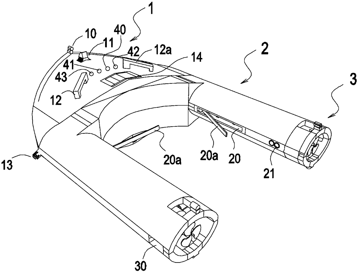
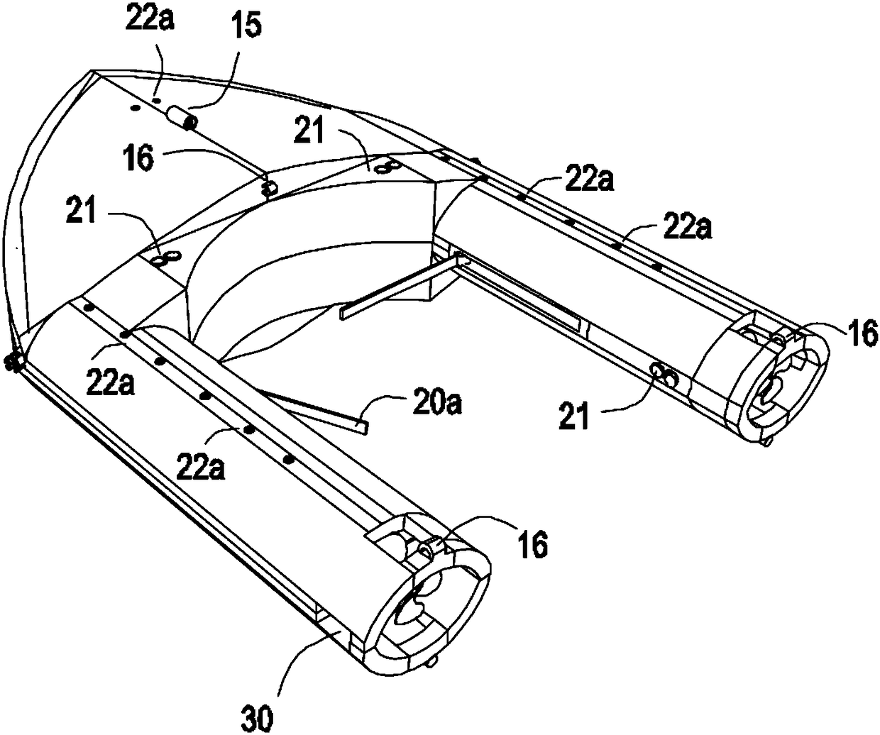
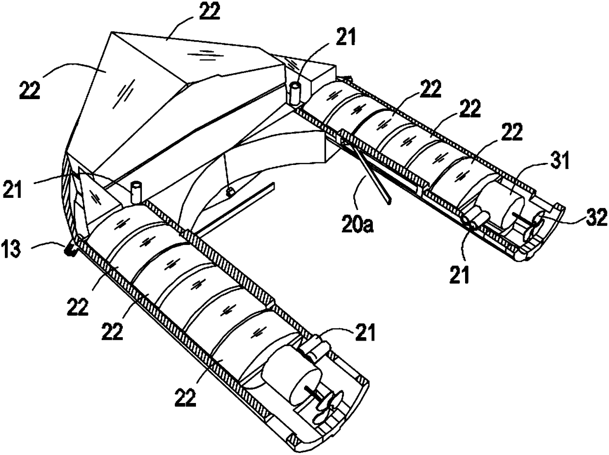
[0033] Embodiments of the present invention will be described in detail below in conjunction with the accompanying drawings.

[0034] In the description of the present invention, it should be understood that the terms "upper", "lower", "left", "right", "front", "rear", "inner", "outer" etc. indicate orientation or positional relationship It is based on the orientation or positional relationship shown in the drawings, or the orientation or positional relationship that is usually placed when the product of the present invention is used, or the orientation or positional relationship that is commonly understood by those skilled in the art, and is only for the convenience of describing the present invention and Simplified descriptions, rather than indicating or implying that the device or element referred to must have a particular orientation, be constructed and operate in a particular orientation, and therefore should not be construed as limiting the invention.

[0035] In additio...


PUM


Abstract

The invention discloses water area rescue equipment. The water area rescue equipment comprises a rescue cabin body, and the rescue cabin is composed of a cabin head, a cabin body and a cabin tail. A wireless remote control system, a power battery, an air sucking and exhausting system and a first submergence system are arranged in the cabin head. The wireless remote control system is used for receiving wireless signals and sending out corresponding instructions through calculation. A second submergence system and a rotating mechanical arm are arranged in the cabin body. The first and second submergence systems are connected with the air sucking and exhausting system by the wireless remote control system, and the rotating mechanical arm is connected with a driving motor to control the opening and closing of the rotating mechanical arm by the wireless remote control system. A power system is installed in the cabin tail, and the power system is connected with the power battery through thewireless remote control system. According to the water area rescue equipment, a rescue mechanical arm can be remotely controlled to carry out rescue instead of rescue or searching under all-weather and all-terrain entering water for rescuers, so that the rescuers are prevented from accidental accidents in the rescue process.

Description

technical field [0001] The invention relates to emergency rescue equipment, in particular to water area rescue equipment. Background technique [0002] Water rescue is a task often faced by fire officers and soldiers. The flood fighting and rescue, disposal of jumping into rivers, wading, and salvage of drowned remains are collectively referred to as "water rescue". [0003] At present, when fire officers and soldiers participate in water rescue, they mainly rely on boats such as life buoys or assault boats. Rescuers drive boats such as assault boats to approach the rescued people trapped in the water, drag them onto the boat or throw a lifebuoy with a tow rope with bare hands, let the rescued climb up on the lifebuoy and drag them back to a safe area. Large, low rescue efficiency. [0004] In addition, due to the wide variety of rescue environments and the different situations of the rescued persons, sometimes the rescuers are faced with the situation that they cannot use...

Claims


Application Information

Patent Timeline
Patent Type & Authority Applications(China)
IPC IPC(8): B63C9/02
CPCB63C9/02
Inventor 朱曾华
Owner 四川领格智造科技有限公司
Why Eureka
Try Eureka