Cross-conveying heat treatment quenching trough mechanism

A horizontal conveying and quenching tank technology, applied in heat treatment equipment, quenching devices, manufacturing tools, etc., can solve the problems of face and hand injuries, hidden dangers, etc., and achieve good results

Inactive Publication Date: 2018-09-28
DONGGUAN LIANZHOU INTPROP OPERATION MANAGEMENT CO LTD
View PDF4 Cites 0 Cited by
  • Summary
  • Abstract
  • Description
  • Claims
  • Application Information

AI Technical Summary

Problems solved by technology

[0002] The existing quenching tank is an ordinary tank body, in which water or oil is added, and the heated workpiece is directly put into the water or oil in the tank for cooling, so as to achieve cooling. However, it manually puts the workpiece When entering, a large amount of steam will be generated, and it is easy to injure people's face and hands directly, which poses a safety hazard

Method used


Image

  • Cross-conveying heat treatment quenching trough mechanism

Examples


Embodiment Construction

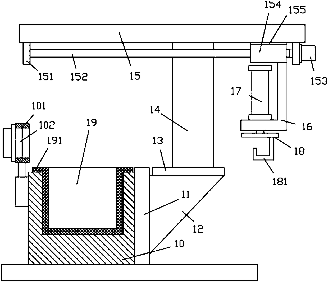
[0012] Examples, see e.g. figure 1 As shown, a heat treatment quenching tank mechanism for horizontal conveyance includes a quenching tank 10, a connecting column 11 is fixed on one side outer wall of the quenching tank 10, and a side connecting block 12 is fixed on the side wall of the connecting column 11, A fixed connection plate 13 is fixed on the side connection block 12, a vertical support plate 14 is fixed in the middle of the fixed connection plate 13, a horizontal plate 15 is fixed on the top of the vertical support plate 14, and the left end of the horizontal plate 15 is at the bottom of the quenching tank 10 Above, the right end of the transverse plate 15 is outside the right side of the quenching tank 10, the left and right ends of the bottom surface of the transverse plate 15 are fixed with support plates 151, and the two ends of the transversely moving screw 152 are hinged on the two support plates 151, one of which A mobile motor 153 is fixed on the outer side w...


PUM


Abstract

The invention discloses a cross-conveying heat treatment quenching trough mechanism which comprises a quenching trough. A connecting column is fixed onto one side outer wall of the quenching trough; aside connecting block is fixed to a side wall of the connecting column; a fixed connecting plate is fixed onto the side connecting block; a vertical supporting plate is fixed to the middle of the fixed connecting plate; a horizontal plate is fixed to the top end of the vertical supporting plate; the left end of the horizontal plate is located above the quenching trough; the right end of the horizontal plate is located on the outer part of the right side of the quenching trough; support plates are fixed to the left end and the right end of the bottom surface of the horizontal plate; two ends of a horizontal movement screw rod are hinged onto the two support plates; a moving motor is fixed onto an outer side wall of one support plate; an output shaft of the moving motor is a spline shaft and is inserted into a spline hole in one end of the horizontal movement screw rod; and a moving block is in screw joint into the horizontal movement screw rod. According to the cross-conveying heat treatment quenching trough mechanism provided by the invention, a workpiece on a pothook can be automatically placed into an inner container so as to be quickly cooled through a liquid in the inner container, so that quenching is realized, and the cross-conveying heat treatment quenching trough mechanism is safe and good in effect.

Description

Technical field: [0001] The invention relates to the technical field of heat treatment equipment, and more specifically relates to a heat treatment quenching tank mechanism for transverse conveyance. Background technique: [0002] The existing quenching tank is an ordinary tank body, in which water or oil is added, and the heated workpiece is directly put into the water or oil in the tank for cooling, so as to achieve cooling. However, it manually puts the workpiece When entering, a large amount of steam will be generated, and it is easy to injure people's face and hands directly, which poses a safety hazard. Invention content: [0003] The purpose of the present invention is to overcome the deficiencies of the prior art and provide a heat treatment quenching tank mechanism for horizontal conveyance, which can automatically put the workpiece on the hook into the inner container, and realize quenching through the rapid cooling of the liquid in the inner container. It is sa...

Claims


Application Information

Patent Timeline
Patent Type & Authority Applications(China)
IPC IPC(8): C21D1/63
CPCC21D1/63
Inventor 徐亚维
Owner DONGGUAN LIANZHOU INTPROP OPERATION MANAGEMENT CO LTD
Why Eureka
Try Eureka