
Pressure limiting valve applied to water supply pipeline

A technology for pressure limiting valves and water supply pipes, applied in the field of pressure limiting valves, which can solve problems such as disconnection of pipeline joints, damage to water facilities of valves, and normal use of water terminals that are not used.

Pending Publication Date: 2018-09-28
RIFENG ENTERPRISE FOSHAN CO LTD +2
View PDF0 Cites 2 Cited by
  • Summary
  • Abstract
  • Description
  • Claims
  • Application Information

AI Technical Summary

Problems solved by technology

[0002] With the continuous acceleration of the urbanization process, the water supply pipeline system has become increasingly complex. In order to meet the water supply requirements of high-rise buildings, the water pressure of the water supply pipeline system has also become higher and higher. High water pressure will pose safety hazards, prone to pipeline rupture and leakage, affecting the normal use of the pipeline. Affected by factors such as poor exhaust, the water pressure in the pipeline will fluctuate violently, forming a water hammer effect. The road vibrates strongly, the pipe joints are disconnected, and the valves and water facilities are damaged
[0003] Traditional water supply pipeline systems usually only install pressure stabilizing and pressure limiting devices on large main pipelines or the entire water supply pipeline system does not install any pressure stabilizing and pressure limiting devices. For the water terminal, when the water pressure in the pipeline is high, It cannot play the role of stabilizing and limiting the pressure, which is not conducive to the normal use of the water terminal

Method used

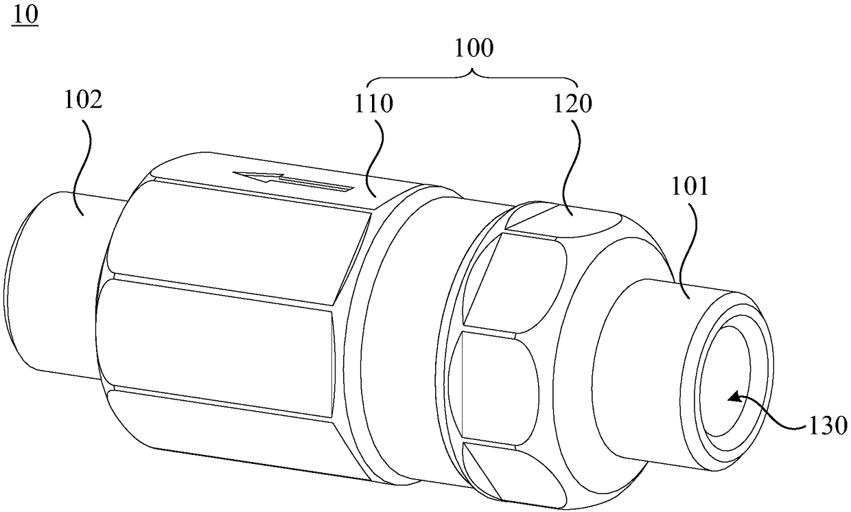
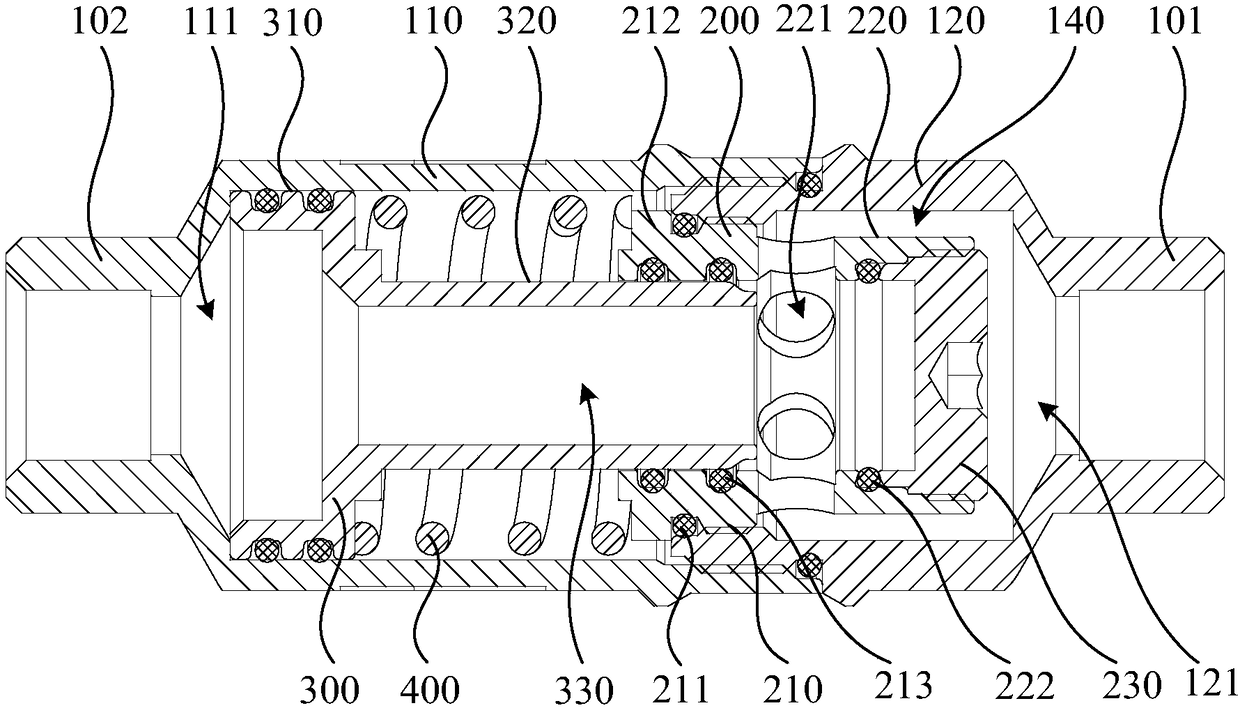
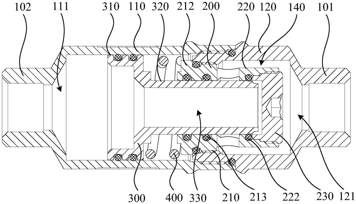

Image

  • Pressure limiting valve applied to water supply pipeline
  • Pressure limiting valve applied to water supply pipeline
  • Pressure limiting valve applied to water supply pipeline

Examples


Embodiment Construction

[0025] In order to make the object, technical solution and advantages of the present invention clearer, the present invention will be further described in detail below in conjunction with the accompanying drawings and specific implementation methods. It should be understood that the specific embodiments described here are only used to explain the present invention, and do not limit the protection scope of the present invention.

[0026]It should be noted that when an element is referred to as being “disposed on” or “fixed on” another element, it may be directly on another element or there may be an intervening element. When an element is referred to as being "fixed on" another element, or "fixedly connected" to another element, it may be detachably fixed or non-detachably fixed therebetween. When an element is referred to as being "connected" or "sealed to" another element, it can be directly connected to the other element or intervening elements may also be present. As used ...


PUM


Abstract

The invention discloses a pressure limiting valve applied to a water supply pipeline. The pressure limiting valve comprises a valve body, a valve base, a piston and elastic reset members. The valve base is provided with a first outer side wall, a second outer side wall and a first communication cavity, and the inner wall of the first communication cavity is provided a first sealing part, through holes and a second sealing part; the piston is provided with a third outer side wall, a fourth outer side wall and a second communication cavity and can reciprocate in the direction from a water inletend to a water outlet end; the elastic reset members abut against the first outer side wall and the third outer side wall separately. When the piston is located at a first position, the fourth outer side wall is in sealed cooperation with the second sealing part, and a first flow channel, the second communication cavity, the first communication cavity, the through holes and a gap channel are all communicated; when the piston is located at a second position, the fourth outer side wall is separately in sealed cooperation with the second sealing part and the first sealing part and seals the through holes. The pressure limiting valve applied to the water supply pipeline can achieve the effects of voltage regulation and pressure limitation, and normal use of a water use end is ensured.

Description

technical field [0001] The invention relates to the technical field of protection devices for water supply pipelines, in particular to a pressure limiting valve applied to water supply pipelines. Background technique [0002] With the continuous acceleration of the urbanization process, the water supply pipeline system has become increasingly complex. In order to meet the water supply requirements of high-rise buildings, the water pressure of the water supply pipeline system has also become higher and higher. High water pressure will pose safety hazards, prone to pipeline rupture and leakage, affecting the normal use of the pipeline. Affected by factors such as poor exhaust, the water pressure in the pipeline will fluctuate violently to form a water hammer effect. The road vibrates strongly, the pipe joints are disconnected, and the valves and water facilities are damaged. [0003] Traditional water supply pipeline systems usually only install pressure stabilizing and pres...

Claims


Application Information

Patent Timeline
IPC IPC(8): E03B7/02E03B7/07
CPCE03B7/02E03B7/07E03B7/075
Inventor 王亮蒋玉林林细勇陈意张名扬苏杰
Owner RIFENG ENTERPRISE FOSHAN CO LTD
Learn More