
Laser power real-time monitoring device

A real-time monitoring and laser technology, applied in the field of ultraviolet lasers, can solve the problems of no effective method, real-time power monitoring of industrial lasers, etc., and achieve the effect of simple structure

Inactive Publication Date: 2018-09-28
SUZHOU INNGU LASER
View PDF0 Cites 0 Cited by
  • Summary
  • Abstract
  • Description
  • Claims
  • Application Information

AI Technical Summary

Problems solved by technology

In addition to the traditional hard parameters such as power and light intensity response pulse, some innovative functions that are easy to operate the laser are gradually being favored. At present, more and more people want to know the real-time power of the laser during operation. There is no effective way to monitor the real-time power of the laser during operation
In the production of ultraviolet lasers, there is currently no device that can monitor the power of various lasers in real time

Method used


Image

  • Laser power real-time monitoring device

Examples


Embodiment Construction

[0009] The following will clearly and completely describe the technical solutions in the embodiments of the present invention with reference to the accompanying drawings in the embodiments of the present invention. Obviously, the described embodiments are only some, not all, embodiments of the present invention. Based on the embodiments of the present invention, all other embodiments obtained by persons of ordinary skill in the art without making creative efforts belong to the protection scope of the present invention.

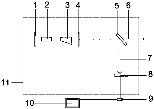
[0010] Laser power real-time monitoring device, including front-end mirror 1, working substance 2, Q-switching device 3, output mirror 4, Brinell window 5, output optical path 6, monitoring optical path 7, photoelectric conversion device 8, calculation program 9, display screen 10, The equipment external cavity 11 is characterized in that most of the equipment devices are arranged in the equipment external cavity 11, the front-end mirror 1 is placed at the left...


PUM


Abstract

The invention discloses a laser power real-time monitoring device, comprising a front end mirror, a working substance, a Q-switching component, an output mirror, a Brinell window, an output optical path, a monitoring optical path, a photoelectric conversion device, a calculation program, a display screen, and an external cavity of the device. The laser power real-time monitoring device is characterized in that the majority of the device components are disposed in the external cavity of the device, the front end mirror is disposed at the leftmost end of the external cavity of the device, the working object and the Q-switching component are disposed behind the front end mirror, the output mirror is disposed at the rear end of the Q-switching component, the output mirror leads to the output optical path, the Brinell window is arranged in the way of the output optical path, the Brinell window splits the monitoring optical path from the output optical path, and the monitoring optical path reaches the photoelectric conversion device. The biggest feature is that the real-time power monitoring of the laser further meets the higher requirements of the related art, and the laser power real-time monitoring device has a simple structure and is suitable for various lasers.

Description

technical field [0001] The invention relates to the field of ultraviolet lasers, in particular to a real-time monitoring device for laser power. Background technique [0002] The development of industrial lasers is becoming more and more mature, and the requirements of customers for lasers are also getting higher and higher. In addition to the traditional hard parameters such as power and light intensity response pulse, some innovative functions that are easy to operate the laser are gradually being favored. At present, more and more people want to know the real-time power of the laser during operation. There is no effective way to monitor the real-time power of the laser during operation. In the production of ultraviolet lasers, there is currently no device that can monitor the power of various lasers in real time. Contents of the invention [0003] The present invention aims at the above problems and provides a device capable of monitoring the power of various lasers i...

Claims


Application Information

Patent Timeline
Patent Type & Authority Applications(China)
IPC IPC(8): G01J1/42
CPCG01J1/42
Inventor 崔晓敏
Owner SUZHOU INNGU LASER
Learn More