Electronic lock

An electronic lock and lock pin technology, applied in the field of electronic locks, can solve the problems of insufficiency and single function, and achieve the effect of easy management

Inactive Publication Date: 2018-01-26
甘炜彦
View PDF0 Cites 0 Cited by
  • Summary
  • Abstract
  • Description
  • Claims
  • Application Information

AI Technical Summary

Problems solved by technology

[0003] The purpose of the present invention is to provide an electronic lock with an automatic timing function that users can use by themselves to solve the problem that the existing electronic lock has a single function and cannot meet the needs of the current Internet era, especially the Internet of Things era.

Method used


Image

  • Electronic lock
  • Electronic lock
  • Electronic lock

Examples


Embodiment Construction

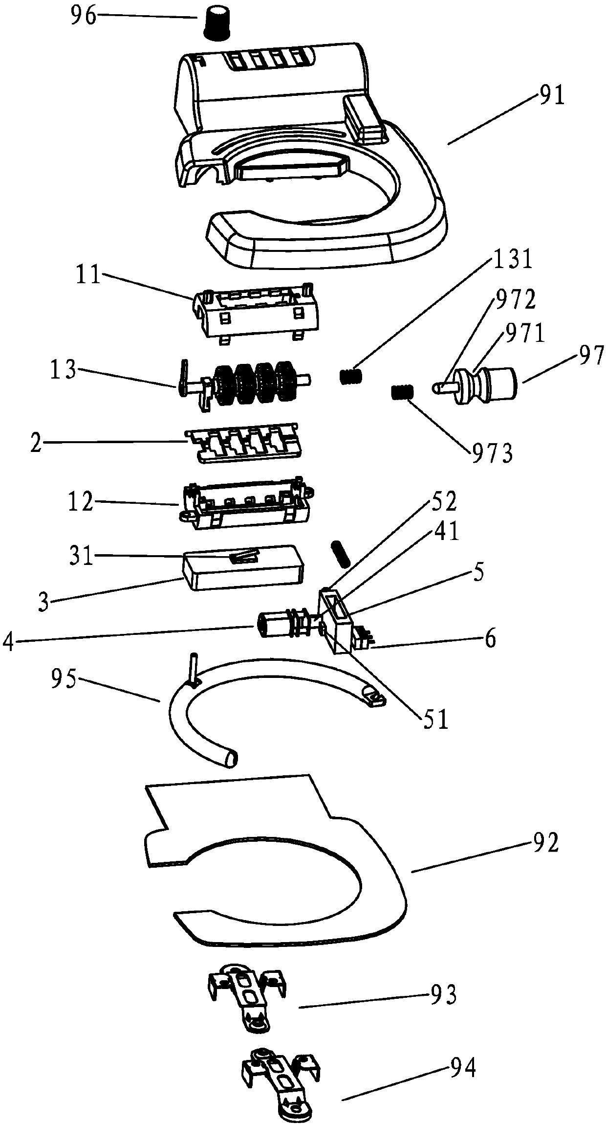
[0025] See figure 1 , is a three-dimensional exploded schematic diagram of a specific embodiment of the electronic lock of the present invention. The electronic lock includes a shell composed of a face shell 91 and a bottom plate 92, a lock arm 95 that can form a mechanical closed loop with the shell, and a lock arm Spring (not shown in the figure), mechanical coded lock and IC (not shown in the figure), described mechanical coded lock comprises the lock housing that is made of upper shell 11 and lower shell 12, password wheel group 13, button 97 and lock Pin 5; a pendulum block 2 whose swing is controlled by the combination wheel group of the mechanical combination lock is provided in the housing, and a pendulum block controlled by the pendulum block and electrically connected to the IC is provided below the pendulum block. The wake-up switch for turning on the IC power.

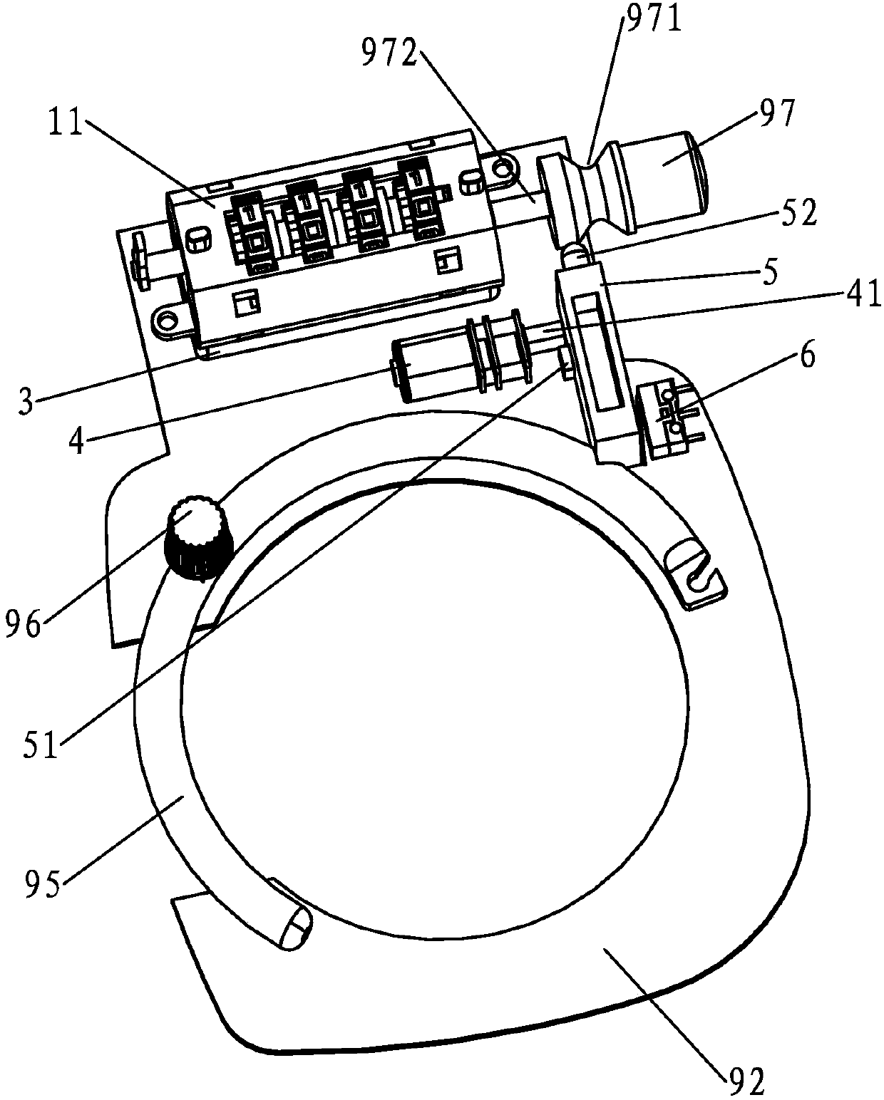
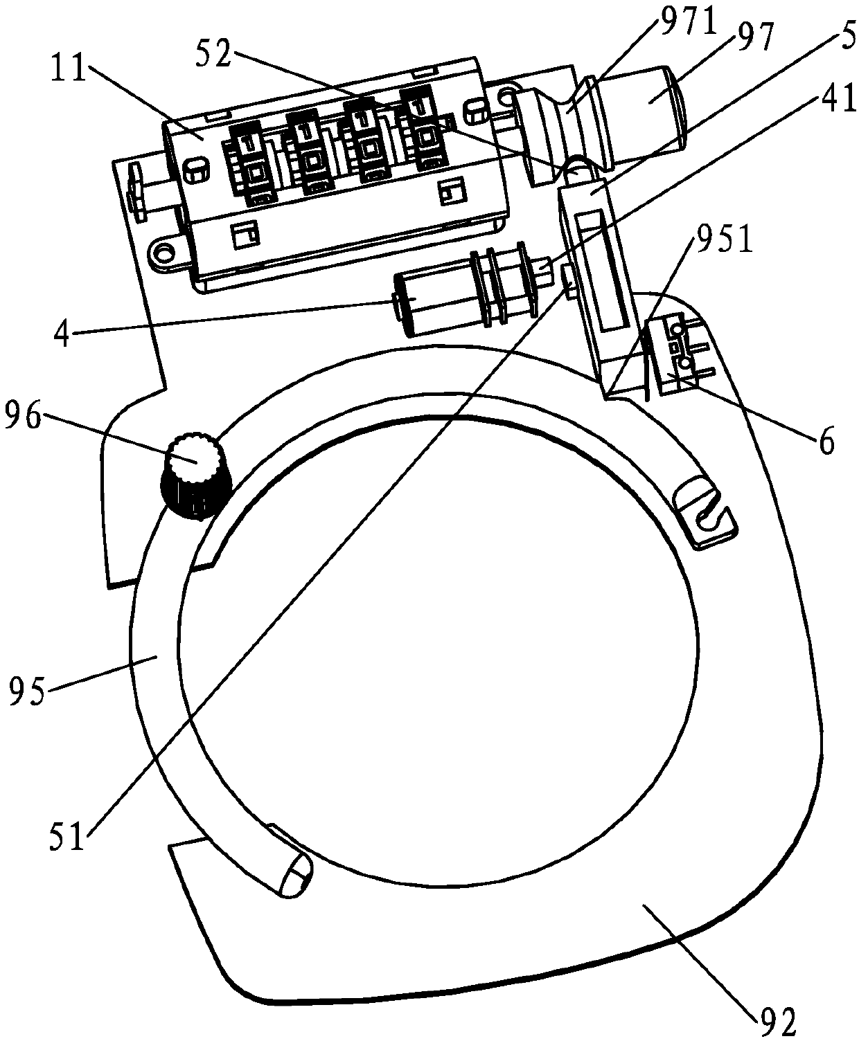
[0026] See Figure 4 ,Yes figure 1 The three-dimensional enlarged view of the middle pendulum block f...


PUM


Abstract

The invention relates to an electronic lock which is used by users via self-service and has an automatic timing function. The electronic lock comprises a shell, a lock arm, a lock arm spring, a mechanical coded lock and an IC, wherein the lock arm can form a mechanical closed loop with the shell; the mechanical coded lock comprises a lock shell formed by an upper shell and a lower shell, a code wheelset, a button and a lock pin; a swing block, swinging of which is controlled by the code wheelset of the mechanical coded lock, is arranged in the shell; an awaken switch which is controlled by theswing block, is electrically connected with the IC and is used for connecting an IC power supply is arranged below the swing block; the movement direction of the button which is arranged in the shellis vertical to the movement direction of the lock pin; an oblique-plane groove matched with the front end of the lock pin is formed in the button; a bayonet matched with the rear end of the lock pinis formed in the lock arm; and a timing switch controlled by the lock pin is arranged in the shell. The electronic lock can establish remote radio contact with a server connected on an internet through a mobile phone, so as to monitor the real-time states of shared equipment and satisfy the demand problems of the internet era at present, especially the internet of things era.

Description

technical field [0001] The invention relates to an electronic lock, in particular to an electronic lock with automatic timing function used by users themselves. Background technique [0002] The existing locks are basically divided into mechanical locks and electronic locks. The electronic locks mainly use motors or electromagnets instead of manpower to start the deadbolt on the basis of mechanical locks to realize the function of opening and closing the locks. Therefore, the existing electronic locks have a single function. It cannot meet the needs of today's Internet era, especially the Internet of Things era. Contents of the invention [0003] The purpose of the present invention is to provide an electronic lock with an automatic timing function that users can use by themselves to solve the problem that existing electronic locks have single functions and cannot meet the needs of the Internet era, especially the Internet of Things era. [0004] The object of the present...

Claims


Application Information

Patent Timeline
Patent Type & Authority Applications(China)
IPC IPC(8): E05B49/00E05B51/00G07C9/00
Inventor 甘炜彦
Owner 甘炜彦
Why Eureka
Try Eureka