A factory boundary odor monitoring gas diversion tank and monitoring device

A diversion groove and odor technology, which is applied in the field of gas diversion grooves and monitoring devices for odor monitoring at the factory boundary, can solve the problems of great influence of sensor temperature, inability to achieve sensor calibration, and low monitoring result accuracy.

Active Publication Date: 2020-02-04
苏州天一信德环保科技有限公司
View PDF8 Cites 0 Cited by
  • Summary
  • Abstract
  • Description
  • Claims
  • Application Information

AI Technical Summary

Problems solved by technology

Traditional real-time monitoring generally exposes the sensor to the air, or uses a fan to suck air into the chassis for monitoring. In this way, since there is no air path, it is impossible to calibrate the sensor with standard gas; at the same time, due to exposure to the air, The sensor is greatly affected by temperature, which makes the monitoring results not very accurate, and the data drifts greatly with the change of seasons, especially in the extremely cold places in the north, which cannot even meet the measurement requirements.

Method used


Image

  • A factory boundary odor monitoring gas diversion tank and monitoring device
  • A factory boundary odor monitoring gas diversion tank and monitoring device
  • A factory boundary odor monitoring gas diversion tank and monitoring device

Examples


Embodiment Construction

[0022] The following will clearly and completely describe the technical solutions in the embodiments of the present invention with reference to the accompanying drawings in the embodiments of the present invention. Obviously, the described embodiments are only some, not all, embodiments of the present invention. Based on the embodiments of the present invention, all other embodiments obtained by persons of ordinary skill in the art without making creative efforts belong to the protection scope of the present invention.

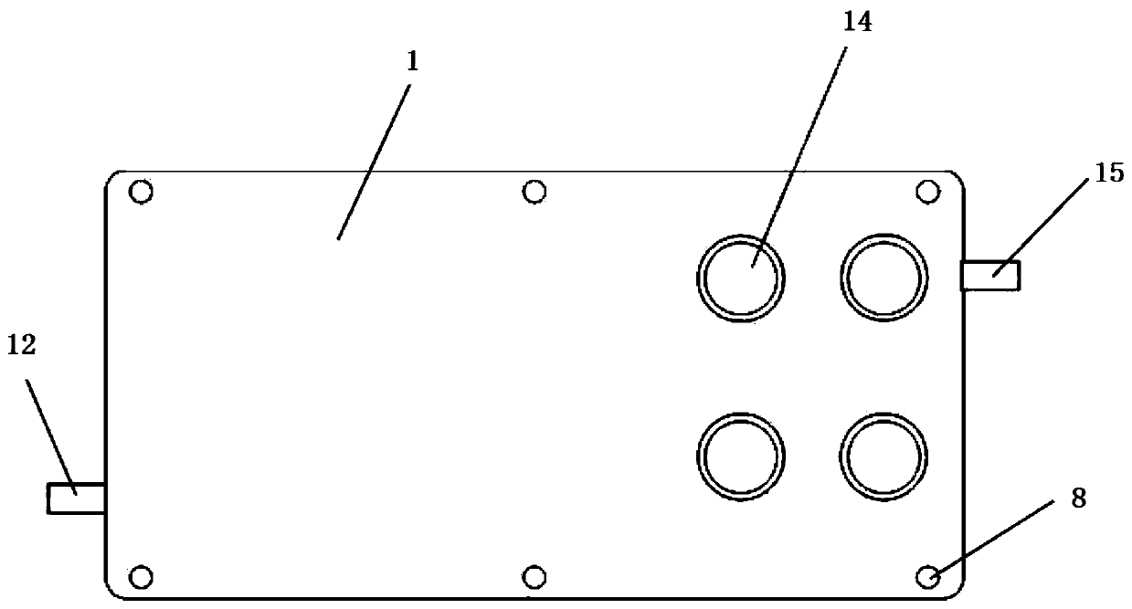
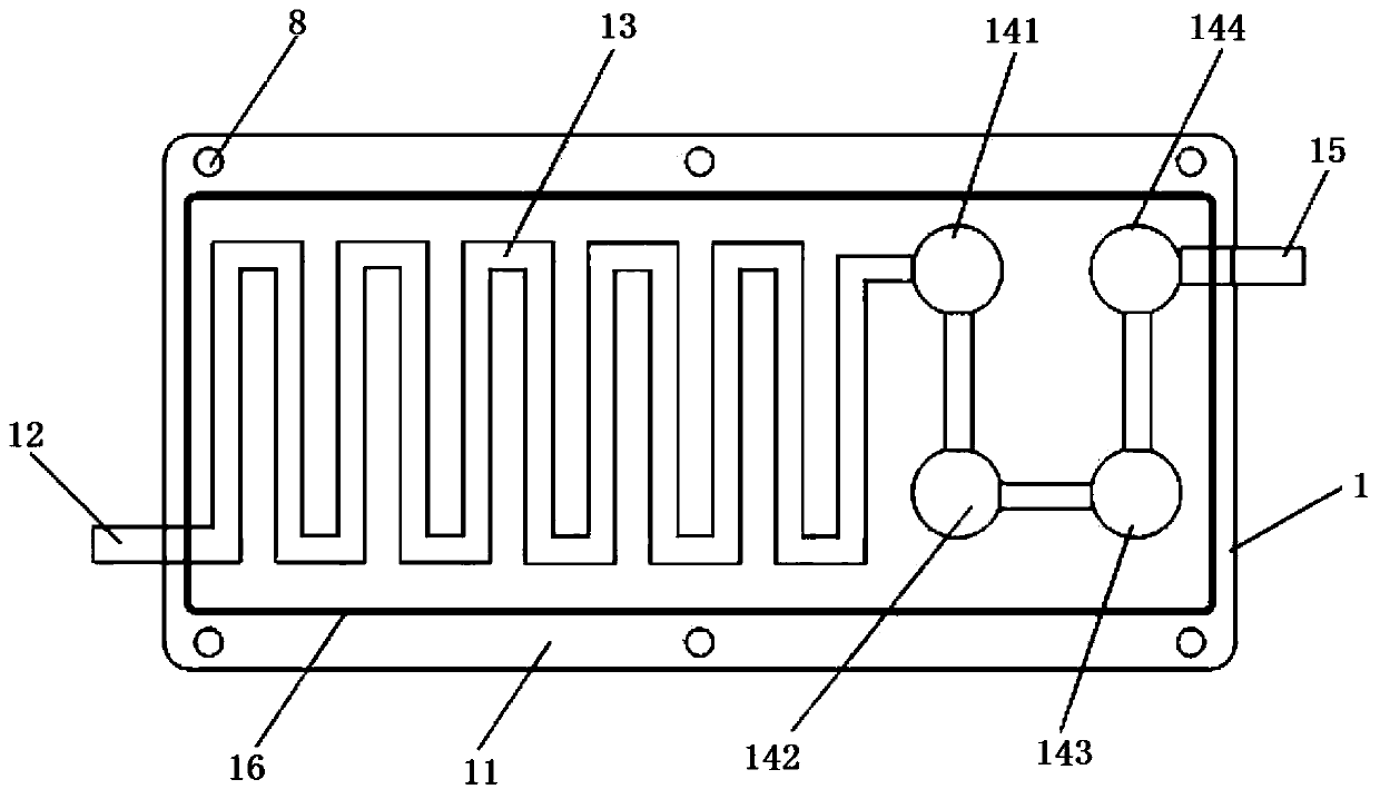
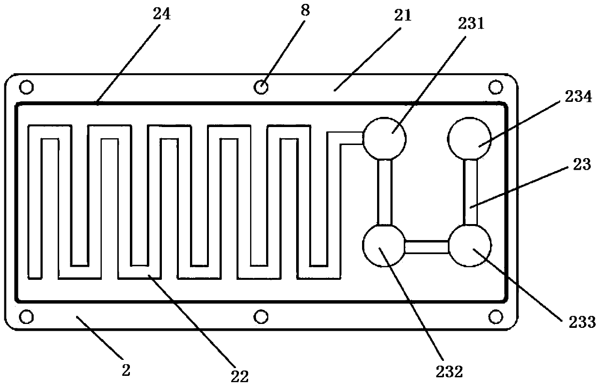
[0023] Such as Figure 1 to Figure 3 As shown, a factory boundary odor monitoring gas diversion tank 3 according to the present invention includes: an upper cover plate 1 and a lower cover plate 2 fixedly connected thereto, wherein the upper cover plate 1 includes an upper cover plate shell 11 and the air inlet 12, the upper preheating guide tank 13, the upper measuring tank assembly 14, and the air outlet 15 arranged on the housing, wherein one end of the air...


PUM


Abstract

The invention discloses a factory bound odor monitoring gas flow guiding groove. The factory bound odor monitoring gas flow guiding groove comprises an upper cover plate and a lower cover plate whichis fixedly connected with the upper cover plate, wherein the upper cover plate comprises an upper cover plate shell, a gas inlet hole, an upper preheating flow guiding groove, an upper measuring groove assembly and a gas outlet hole; the gas inlet hole, the upper preheating flow guiding groove, the upper measuring groove assembly and the gas outlet hole are formed in the shell; one end of the gasinlet hole extends out of the outer side of the upper cover plate shell while the other end of the gas inlet hole is connected with the preheating flow guiding groove; the preheating flow guiding groove is connected with the upper measuring groove assembly; the upper measuring groove assembly is connected with the gas outlet hole; the lower cover plate comprises a lower cover plate shell, a lowerpreheating flow guiding groove and a lower measuring groove assembly; the lower preheating flow guiding groove and the lower measuring groove assembly are arranged on the lower cover plate shell; thestructure and the position of the lower preheating flow guiding groove are matched with those of the upper preheating flow guiding groove; and the structure and the position of the lower measuring groove assembly are matched with those of the upper measuring groove assembly. The invention further provides a monitoring device which uses the flow guiding groove. It can be ensured that an electrochemical sensor works in a stable temperature range.

Description

technical field [0001] The invention relates to the technical field of odor monitoring, in particular to a gas diversion tank and a monitoring device for odor monitoring at the factory boundary. Background technique [0002] Real-time monitoring of odor at the factory boundary, the main monitoring indicators are H 2 S, NH 3 and other odorous gases that can cause adverse reactions. This kind of monitoring basically adopts the measuring principle of electrochemistry. Traditional real-time monitoring generally exposes the sensor to the air, or uses a fan to suck air into the chassis for monitoring. In this way, since there is no air path, it is impossible to calibrate the sensor with standard gas; at the same time, due to exposure to the air, Sensors are greatly affected by temperature, which makes the accuracy of monitoring results not high, and the data drifts greatly with seasonal changes, especially in extremely cold places in the north, which cannot even meet the measur...

Claims


Application Information

Patent Timeline
Patent Type & Authority Patents(China)
IPC IPC(8): G01N27/26
CPCG01N27/26
Inventor 赵贵王淑建周建彬倪俊
Owner 苏州天一信德环保科技有限公司
Why Eureka
Try Eureka