
Laser ranging optical axis consistency dynamic calibration method and system

A technology of laser ranging and dynamic calibration, applied in the field of laser measurement, it can solve the problems such as the decrease of the measurement range and accuracy of the ranging system, the poor consistency of the optical axis parallelism and the optical axis, so as to avoid the need for regular return to the factory for adjustment and realize distance measurement. system, the effect of improving continuous working time and environmental adaptability

Pending Publication Date: 2018-09-28
LUOYANG INST OF ELECTRO OPTICAL EQUIP OF AVIC
View PDF0 Cites 8 Cited by
  • Summary
  • Abstract
  • Description
  • Claims
  • Application Information

AI Technical Summary

Problems solved by technology

[0004] The purpose of the present invention is to provide a laser ranging optical axis consistency dynamic calibration method and system to solve the problem of sharp decline in the measurement range and accuracy of the ranging system caused by poor optical axis consistency caused by the deterioration of the parallelism of the optical axis question

Method used


Image

  • Laser ranging optical axis consistency dynamic calibration method and system
  • Laser ranging optical axis consistency dynamic calibration method and system
  • Laser ranging optical axis consistency dynamic calibration method and system

Examples


Embodiment Construction

[0025] The present invention will be further described in detail below in conjunction with the drawings.

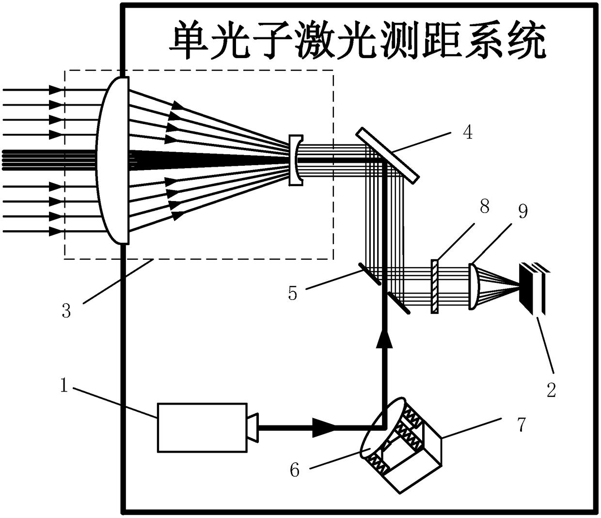
[0026] The present invention provides a laser ranging system, such as figure 1 As shown, it includes a laser 1, a transmitting optical path, a receiving optical path, and a signal receiving and processing device 2. The optical path is provided with a laser transceiver lens 3, a first fixed mirror 4, a second fixed mirror, an FSM mirror 6, a piezoelectric deflection pendulum Stage 7, narrow band filter 8, and receiving optical assembly 9.

[0027] Among them, the second fixed reflector is a hollow reflector 5; the emitted light of the emission light path is emitted from the laser 1 and reflected by the FSM reflector 6, passes through the hollow part of the hollow reflector 5, is reflected by the first fixed reflector 4, and is transmitted and received from the laser Lens 3 is sent out.

[0028] The reflected light of the receiving optical path passes through the laser transceive...


PUM


Abstract

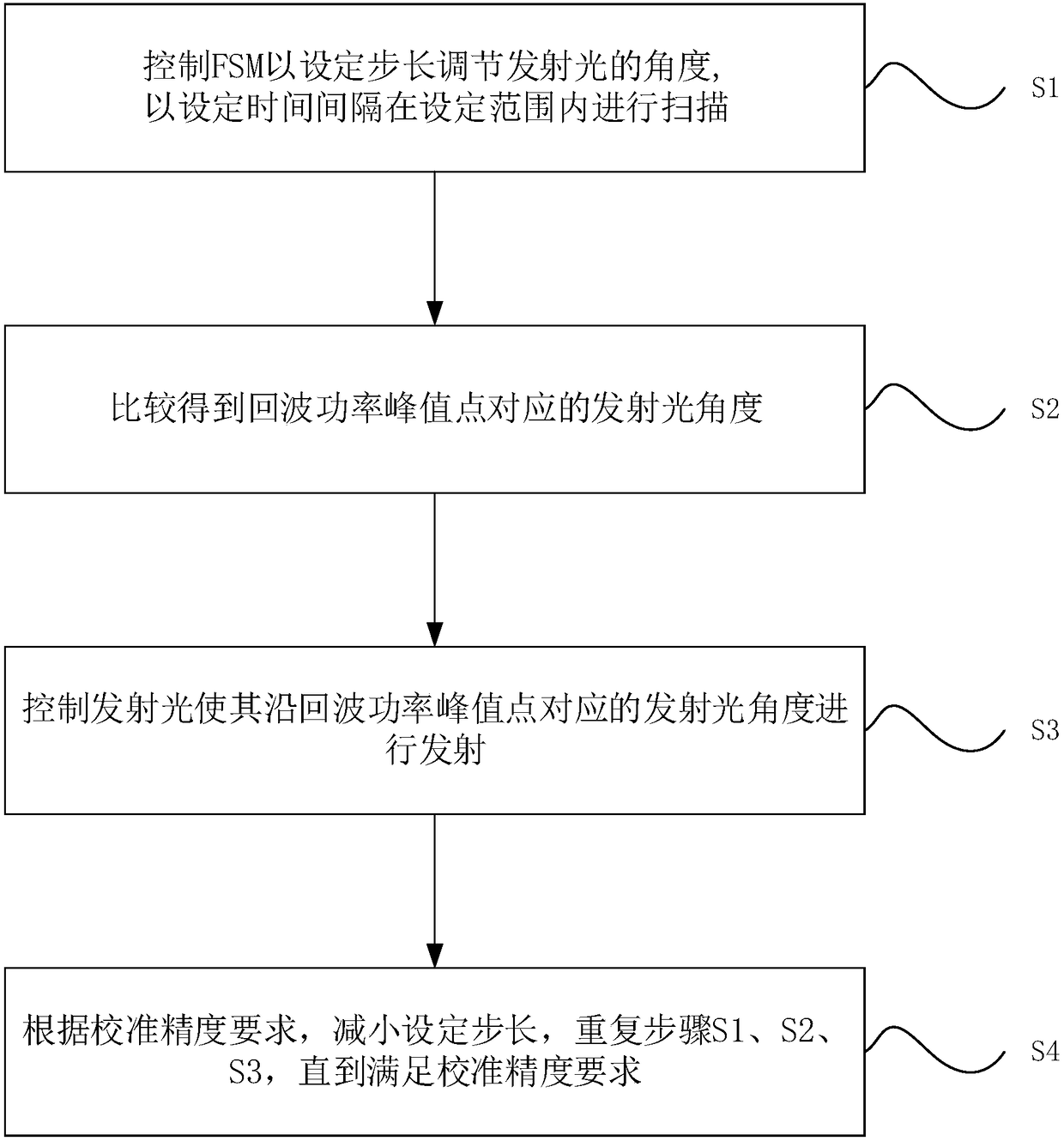
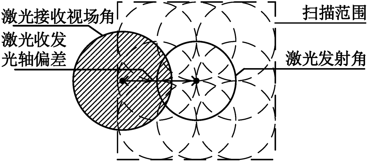
The invention relates to the technical field of laser measurement, in particular to a laser ranging optical axis consistency dynamic calibration method and system. The laser ranging system comprises alaser 1, an emission light path, a receiving light path and a signal receiving and processing device 2, the light path is provided with a laser receiving and transmitting lens 3, a first fixed reflecting mirror 4, a hollow reflecting mirror 5, an FSM reflecting mirror 6, a piezoelectric deflection table 7, a narrow-band light filter 8 and a receiving optical assembly 9. The transmitting light path is adjusted for preset manner scanning, and the emission angle corresponding to the echo power peak value point meeting the system receiving-emitting optical axis error range requirement can be obtained through analysis and comparison, the piezoelectric deflection table is used for driving the FSM reflecting mirror to deflect, the emission light path is controlled to emit laser along the angle corresponding to the power peak value point, and therefore the consistency of the laser receiving-emitting optical axis is guaranteed, and the problem that the measurement range and precision of the ranging system are sharply reduced due to the fact that the parallelism of the laser receiving-emitting optical axis is degraded is solved.

Description

Technical field [0001] The invention relates to the technical field of laser measurement, in particular to a dynamic calibration method and system for laser ranging optical axis consistency. Background technique [0002] As a carrier of information or energy, laser has been widely used in the fields of countermeasures, measurement, space communication and display. In this type of laser application system, it involves the rapid and precise adjustment of the laser transmission optical path, and the adjustment accuracy and speed are directly determined Whether the performance index of the laser system can be achieved. [0003] In the long-distance laser ranging system, the consistency of the laser receiving and emitting axis has an important influence on the performance of ranging and the realization of ranging accuracy. Due to the influence of long-distance environmental vibration, temperature and other factors, the parallelism of the laser receiving and emitting axis will deteriora...

Claims


Application Information

Patent Timeline
IPC IPC(8): G01S7/497G01S17/08
CPCG01S7/497G01S17/08
Inventor 陈水忠周研
Owner LUOYANG INST OF ELECTRO OPTICAL EQUIP OF AVIC
Learn More