Optical axis fine tuning method of laser range finder and laser range finder

A technology of laser range finder and optical axis, which is applied in the field of laser range finder, can solve the problem of high cost, achieve the effect of eliminating regular return to factory adjustment, improving continuous working time and environmental adaptability

Pending Publication Date: 2022-04-19
SHENZHEN MAMMOTH ELECTRONIC CO LTD
View PDF2 Cites 0 Cited by
  • Summary
  • Abstract
  • Description
  • Claims
  • Application Information

AI Technical Summary

Problems solved by technology

[0006] The inventors have found that the above-mentioned fine adjustments to the optical axis are all completed by electric control, which is costly

Method used


Image

  • Optical axis fine tuning method of laser range finder and laser range finder
  • Optical axis fine tuning method of laser range finder and laser range finder
  • Optical axis fine tuning method of laser range finder and laser range finder

Examples


Embodiment Construction

[0029]The technical solutions in the embodiments of the invention will be clearly and completely described below in conjunction with the accompanying drawings in the embodiments of the invention. Obviously, the described embodiments are only part of the embodiments of the present invention, not all of them. Based on the embodiments of the present invention, all other embodiments obtained by persons of ordinary skill in the art without making creative efforts belong to the protection scope of the present invention.

[0030] The terms "first", "second", and "third" in the present invention are only used for descriptive purposes, and cannot be understood as indicating or implying relative importance or implicitly specifying the quantity of indicated technical features. Thus, features defined as "first", "second", and "third" may explicitly or implicitly include at least one of these features. In the description of the present invention, "plurality" means at least two, such as two...


PUM


Abstract

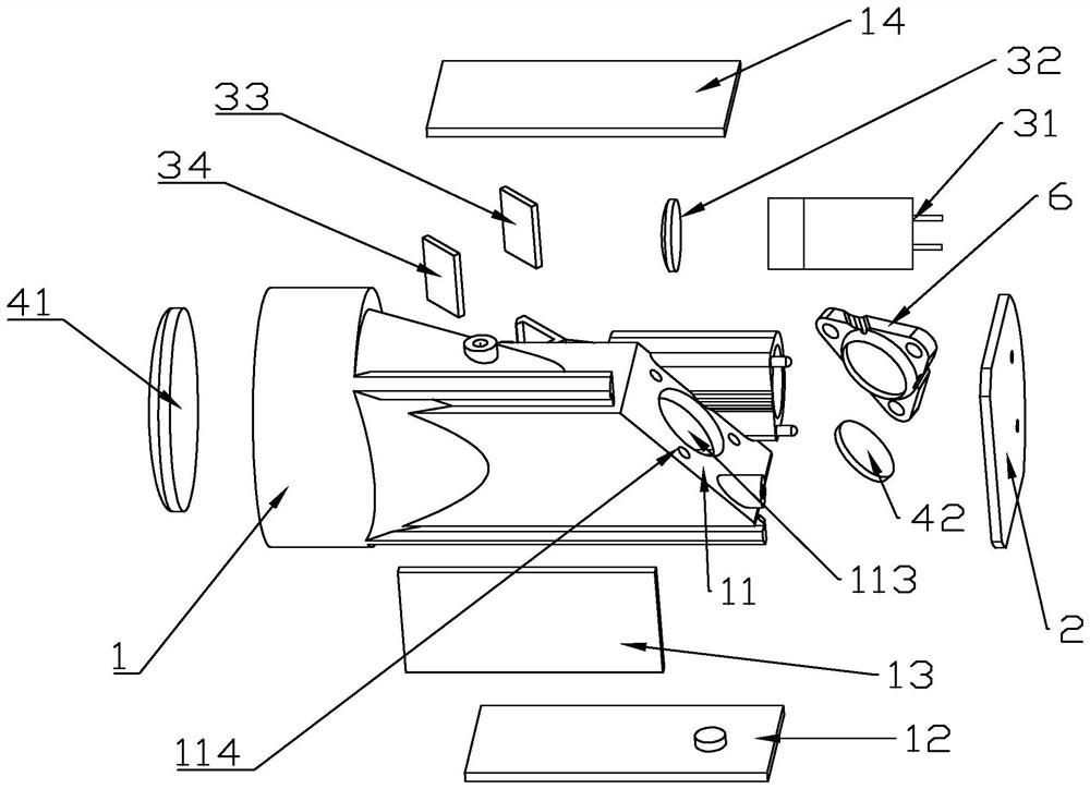
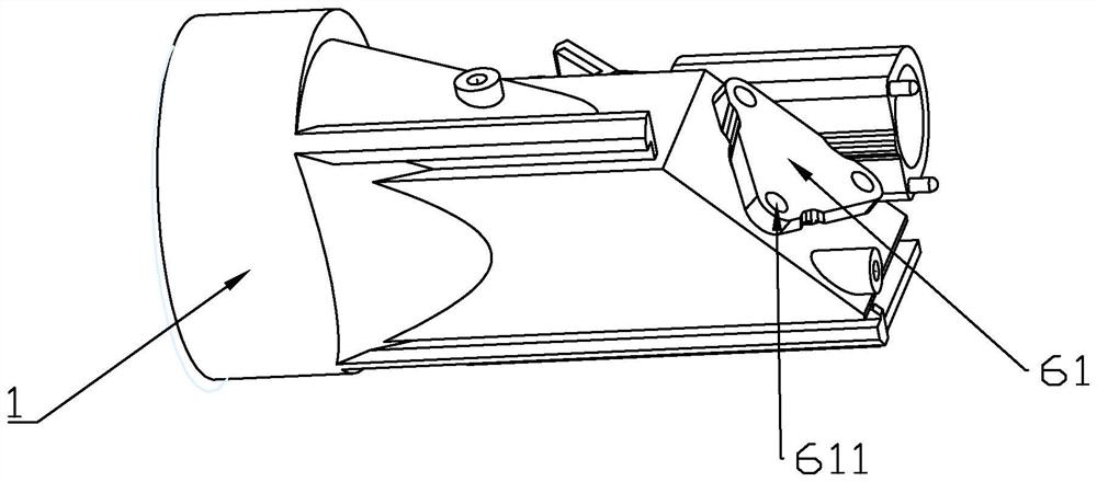
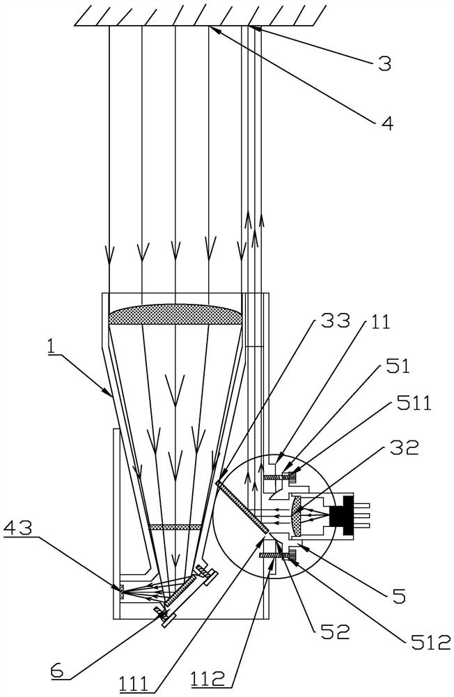
The optical axis fine tuning method comprises a light path base main body, a PCB (Printed Circuit Board), a transmitting light path and a receiving light path, and comprises the following steps of: installing a light path element on the transmitting light path or the receiving light path at the center of a pendulum body; a swing bearing hole matched with the swing body is formed in a shell of the optical path base body, and the installation angle of the optical path element is slightly changed by adjusting the swing body to slightly swing in the swing bearing hole, so that the angle of the optical axis is slightly adjusted, and the emitting optical path and the receiving optical path are kept coaxial.

Description

technical field [0001] The invention relates to the technical field of laser measurement, in particular to a method for fine-tuning the optical axis of a laser range finder and the laser range finder. Background technique [0002] Laser ranging instrument is an instrument that uses laser to accurately measure the distance of the target (also known as laser ranging). Laser rangefinders have the advantages of simple operation, high measurement accuracy, long range, and strong anti-interference ability, and are widely used in military and civil affairs. A laser rangefinder usually includes a laser emitting system and a laser receiving system, and the two independent optical systems have their own optical axes. When the laser distance measuring instrument is working, it first uses the laser emitting system to emit a beam of laser light to the measured target, and the scattered laser echo is received by the laser receiving system, so as to determine the distance between the meas...

Claims


Application Information

Patent Timeline
Patent Type & Authority Applications(China)
IPC IPC(8): G01S7/481G01S17/08
CPCG01S7/4811G01S17/08
Inventor 王振兴
Owner SHENZHEN MAMMOTH ELECTRONIC CO LTD
Why Eureka
Try Eureka