Eureka AIR delivers breakthrough ideas for toughest innovation challenges, trusted by R&D personnel around the world.

Multiple Field of View Dual Band Optics with Integrated Calibration Source

a dual-band optics and calibration source technology, applied in the field of optical devices, can solve the problems of affecting the design of dual-band systems, and affecting the performance of dual-band systems

Active Publication Date: 2017-11-30
UNTED STATES OF AMERICA AS REPRESENTED BY THE SEC OF THE ARMY
View PDF5 Cites 24 Cited by
  • Summary
  • Abstract
  • Description
  • Claims
  • Application Information

AI Technical Summary

Benefits of technology

The patent describes a solution to create optical devices with diffraction-limited image quality and multiple field of view. It also mentions the use of a calibration target for easy and accurate calibration. The patent describes a specific multiple field of view dual band optical device with a rotating tumbler and two Galilean afocal optical assemblies. The device also includes a flat thermal reference surface for automatic calibration of the detector array. The technical effects of this patent are improved image quality and reduced calibration time for optical devices with multiple field of view and simultaneous operation in both spectral bands.

Problems solved by technology

This “dual band” operation places a great burden on refractive lens designs to maintain color aberration correction over both bands simultaneously.
When the sensor is also required to provide three or four fields of view, optical complexity increases even further.
Design approaches for new dual-band systems can no longer be derived from older generation single-band sensors.
Furthermore, when the system is evaluated for performance in both 3-5 and 8-12 micron spectral bands, it is quickly seen that the chromatic aberrations between the two bands are very disparate and thus the basic design form can not be simply “tweaked” to achieve good performance.
However, these optical assemblies do not offer wide selection of field of view change options, which in fact are referenced as “optional fore-optics” in the aforementioned patent.
This function, too, is complicated by the need for multiple field of view switching and simultaneous operation in two disparate spectral bands.

Method used


Image

  • Multiple Field of View Dual Band Optics with Integrated Calibration Source
  • Multiple Field of View Dual Band Optics with Integrated Calibration Source
  • Multiple Field of View Dual Band Optics with Integrated Calibration Source

Examples


Embodiment Construction

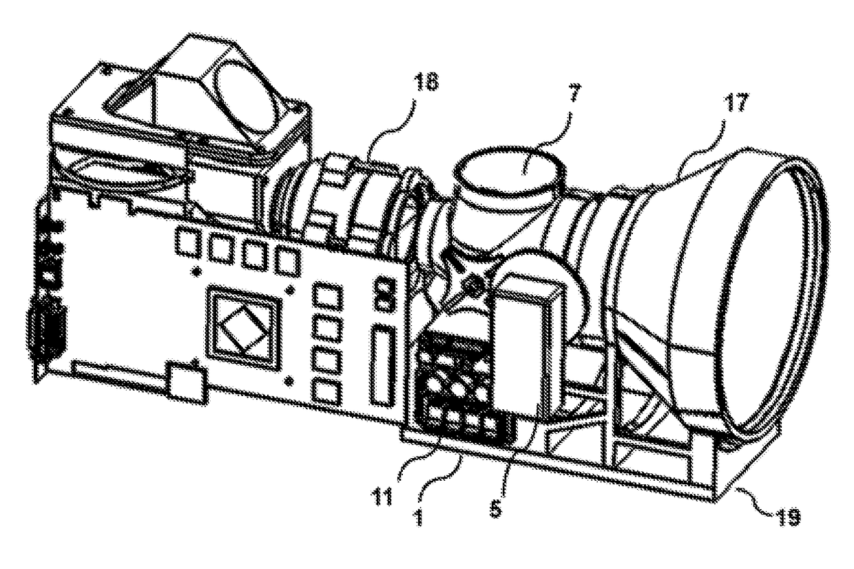
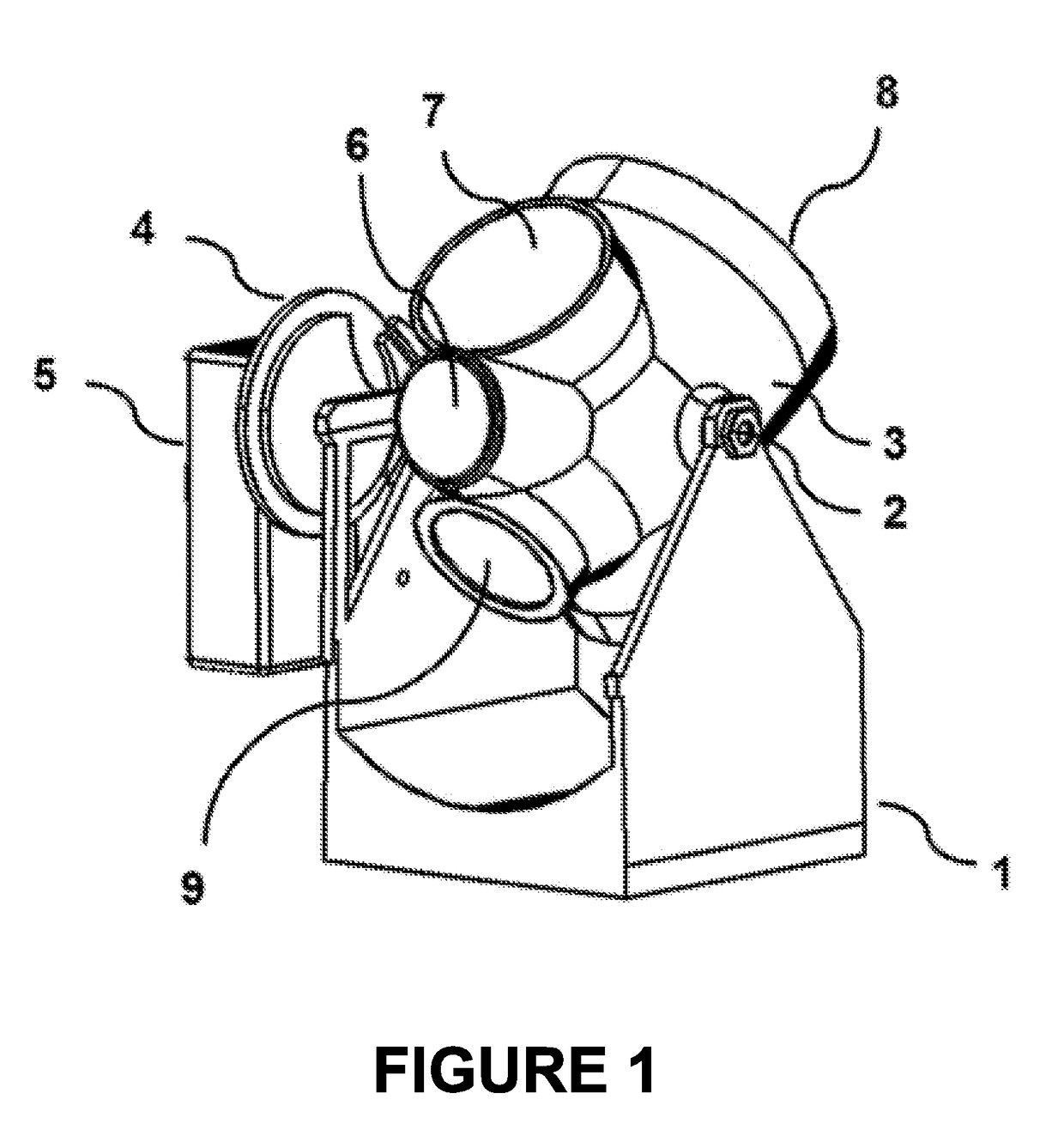
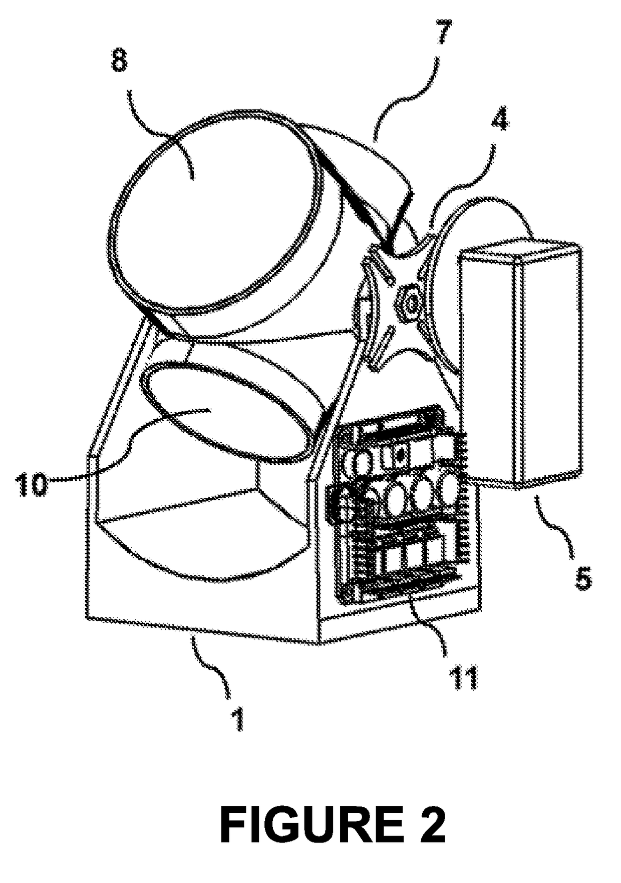
[0014]A multiple field of view dual band optical device with integrated calibration source is disclosed. Such an optical device is modular, and has a rotating electro-mechanical “tumbler” which houses two orthogonal Galilean afocal optical assemblies, as well as at least one uniform temperature source. This modular device is intended to be inserted in front of a camera system which already has an imager optical assembly mated to a detector focal plane array. The disclosed modular device thus serves the purpose of providing to an existing dual-band camera imager up to four new optical fields of view, as well as an integral calibration source, all of which can be electro-mechanically selected for viewing by a host camera imager.

[0015]FIG. 1 shows a side profile view of an exemplary multiple field of view dual band optical device with integrated calibration source. The base unit housing 1 provides support for the pivot bearings 2 which in turn allows the tumbler mechanism 3 to rotate c...


PUM


Abstract

A multiple field of view dual band optical device with integrated calibration source is disclosed. Such an optical device is modular, and has a rotating electro-mechanical “tumbler” which houses two orthogonal Galilean afocal optical assemblies as well as at least one uniform temperature source. This modular device is intended to be inserted in front of a camera system which already has an imager optical assembly mated to a detector focal plane array. The disclosed modular device thus serves the purpose of providing to an existing dual-band camera imager up to four new optical fields of view as well as an integral calibration source, all of which can be electro-mechanically selected for viewing by a host camera imager.

Description

GOVERNMENT INTEREST[0001]The invention described herein may be manufactured, used, sold, imported, and / or licensed by or for the Government of the United States of America.FIELD OF THE INVENTION[0002]This invention is applicable to the field of optical devices, particularly in regards to multiple field of view dual band optics.BACKGROUND OF THE INVENTION[0003]The newest generation of high performance infrared imaging sensor systems employ staring focal plane detector arrays which are sensitive in both the 3-5 micron “mid-wave infrared” and 8-12 micron “long-wave infraredspectral bands. This “dual band” operation places a great burden on refractive lens designs to maintain color aberration correction over both bands simultaneously. When the sensor is also required to provide three or four fields of view, optical complexity increases even further. Design approaches for new dual-band systems can no longer be derived from older generation single-band sensors. For example, U.S. Pat. No...

Claims


Application Information

Patent Timeline
IPC IPC(8): H04N5/232G02B15/14G02B23/16H04N5/33
CPCH04N5/23296G02B15/14G02B23/16H04N5/332G02B23/00H04N23/69H04N23/11
Inventor HALL, JOHN M.WRIGHT, RICHARD A.KOWALEWSKI, BRIAN J.DOTSON, ANDREW J.
Owner UNTED STATES OF AMERICA AS REPRESENTED BY THE SEC OF THE ARMY
Why Eureka
Eureka Blog
Learn More