Automatic detection device of wrapping tape laminated belt

An automatic detection device and technology of wrapping tape, which is applied in the manufacture of electrical components, circuits, cables/conductors, etc., can solve the problems of ensuring the straightening effect of the wrapping tape, avoid uneven wrapping, facilitate inspection, and increase the contact effect. Effect

Active Publication Date: 2018-09-28
ANHUI CABLE
View PDF5 Cites 1 Cited by
  • Summary
  • Abstract
  • Description
  • Claims
  • Application Information

AI Technical Summary

Problems solved by technology

The existing wrapping machine can no longer guarantee the straightening effect of the wrapping tape when inspecting the wrapping tape, and when the wrapping tape is rewound, the wrapping tape will form a curl or superposition effect on the surface of the reel

Method used


Image

  • Automatic detection device of wrapping tape laminated belt
  • Automatic detection device of wrapping tape laminated belt
  • Automatic detection device of wrapping tape laminated belt

Examples


Embodiment 1

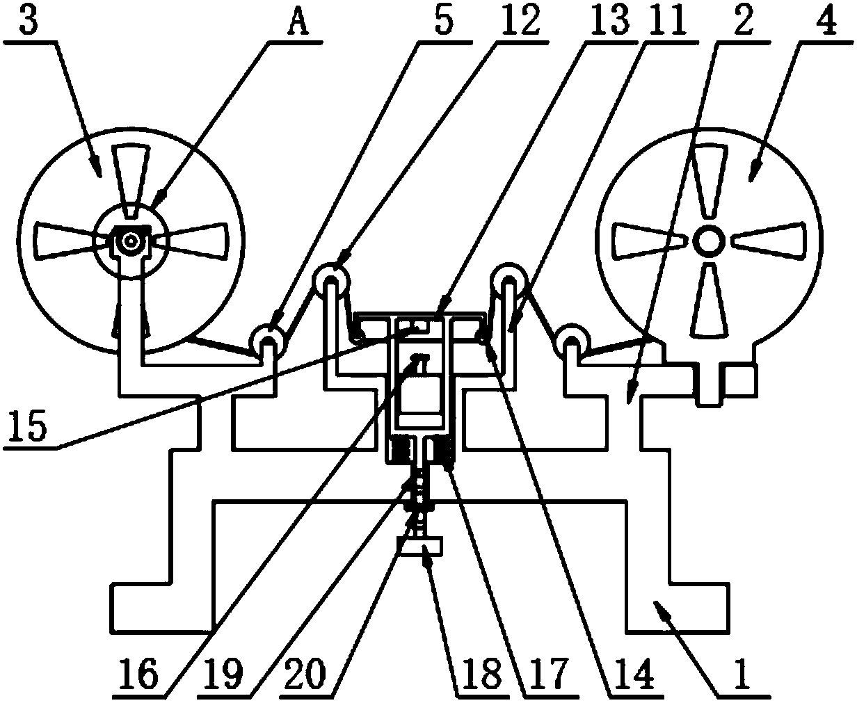
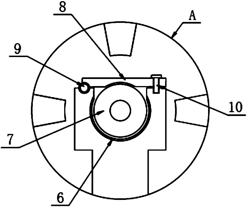
[0025] The present invention provides such Figure 1-4 A wrapping tape stacking automatic detection device shown includes a bracket 1, a frame block 2 is provided on both sides of the top of the frame block 1, and a tape reel 3 is provided on one side of the top of the frame block 2. The other side of the top of the block 2 is provided with a tape take-up reel 4, and one side of the tape release reel 3 and the tape take-up reel 4 is provided with a first reversing roller 5, and between the tape release reel 3 and the frame block 2 is a A rubber ring 6, a rotary rod 7 is provided on the outside of the tape release reel 3, a pressure plate 8 is provided on the top of the rotary rod 7, a bearing 9 is provided at one end of the pressure plate 8, and a fastening screw 10 is provided at the other end of the pressure plate 8 , the inside of the first reversing roller 5 is provided with a fixed frame 11, the top of the fixed frame 11 is provided with a second reversing roller 12, the ...

Embodiment 2

[0030] The tape release reel 3 is placed correspondingly to the rubber ring 6, one end of the pressing plate 8 is fixedly connected with the bearing 9, the other end of the pressing plate 8 is connected with the frame block 2 through the fastening screw 10, and the pressing plate 8 is fixed by the fastening screw 10. Fasten on the top of the frame block 2, and then make the tape reel 3 stable.

[0031] The bottom of the take-up reel 4 is provided with a protruding rod, and the protruding rod is matched with the frame block 2. A wrapping tape is arranged between the unwinding reel 3 and the take-up reel 4, and the first reversing roller 5 , the second redirection roller 12 and the third redirection roller 14 are all attached to the surface of the wrapping belt, and the effect of the first redirection roller 5, the second redirection roller 12 and the third redirection roller 14 is used to wrap around Tighten the straps to prevent the wrapping straps from coming off.

[0032] T...


PUM


Abstract

The invention discloses an automatic detection device of a wrapping tape laminated belt. The automatic detection device comprises a support, wherein frame blocks are arranged at two sides of the top of the support, a tape placement disc is arranged at one side of the top of each frame block, a tape receiving disc is arranged at the other side of the top of each frame block, a first turning rolleris arranged at one side of each of the tape placement disc and the tape receiving disc, a rubber ring is arranged between the tape receiving disc and the frame rack, a rotation rod is arranged at an outer side of the tape placement disc, and a press plate is arranged at the top of the rotation rod. By arranging a lifting rack, a wrapping tape is favorably fastened, so that the wrapping tape is convenient to check, the tape placement disc and the tape receiving tape are needed to be assembled during detection of the wrapping tape, a fastening screw rod is loosen, the press is rotated by takinga bearing as an axis, the rotation rod is placed at the top o the rubber ring, the press plate is fastened at the tops of the frame blocks by the fastening screw rod, so that the tape placement disc is stabilized, and a frame of the tape receiving disc is fixed by matching of a convex rod at the bottom of the tape receiving disc and the bottoms of the frame block.

Description

technical field [0001] The invention relates to the technical field of wrapping machines, in particular to an automatic detection device for wrapping tape overlapping. Background technique [0002] The wrapping machine is a device for wrapping the inner core of resistance wires and multi-strand twisted wrapping mica tapes, resistance tapes, water blocking tapes, polyester tapes, etc. The existing wrapping machine can no longer ensure the straightening effect of the wrapping tape when inspecting the wrapping tape, and when the wrapping tape is rolled up, the wrapping tape will form a curl or superposition effect on the surface of the winding reel. [0003] Therefore, it is necessary to invent an automatic detection device for wrapping tape to solve the above problems. Contents of the invention [0004] The purpose of the present invention is to provide an automatic detection device for wrapping tape overlapping, which uses the effects of the first changing roller, the seco...

Claims


Application Information

Patent Timeline
Patent Type & Authority Applications(China)
IPC IPC(8): H01B13/26
CPCH01B13/2613
Inventor 张万有夏候东周俊朱元忠高从民徐晓丽陈安鹏李海波
Owner ANHUI CABLE
Why Eureka
Try Eureka