

V-cut light guide plate forming method and V-cut light guide plate forming mold
A molding method and molding mold technology, applied in the field of V-cut light guide plate molding method and V-cut light guide plate molding mold, can solve problems such as molding difficulties, and achieve the effect of reducing the use of colloidal flow methods
- Summary
- Abstract
- Description
- Claims
- Application Information
AI Technical Summary
Problems solved by technology
Method used
Image

Examples
Embodiment Construction
[0031] The present invention provides a V-cut light guide plate forming method and a V-cut light guide plate forming mold. In order to make the purpose, technical solution and effect of the present invention clearer and clearer, the present invention will be further described in detail below with reference to the accompanying drawings and examples. It should be understood that the specific embodiments described here are only used to explain the present invention, not to limit the present invention.
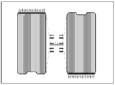
[0032] When the transmission compression mold is processing the ordinary light guide plate (that is, the light guide plate without V-cut structure), it is arranged vertically, that is, figure 1 The arrangement shown in is better, because the glue inlet is set between the two light guide plate molding cavities, and is connected to the long side of the light guide plate molding cavity through the approximately trapezoidal glue inlet flow channel, which is convenient for injecting the...
PUM
 Abstract
Description
Claims
Application Information