Temperature-control probe support and air conditioner

A technology of a temperature control probe and a support part, which is applied in the field of air-conditioning equipment, can solve the problem that the temperature control probe bracket cannot be installed and removed in a stable and fixed state at the same time.

Active Publication Date: 2018-10-02
NINGBO AUX ELECTRIC
View PDF11 Cites 3 Cited by
  • Summary
  • Abstract
  • Description
  • Claims
  • Application Information

AI Technical Summary

Problems solved by technology

[0004] In view of this, the present invention aims to propose a temperature control probe bracket to solve the problem that the exis

Method used


Image

  • Temperature-control probe support and air conditioner
  • Temperature-control probe support and air conditioner
  • Temperature-control probe support and air conditioner

Examples


Embodiment 1

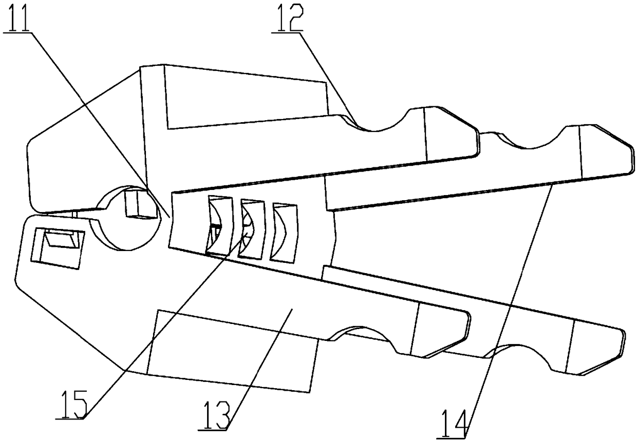
[0045] The temperature control probe bracket includes a clamping assembly 1 and a mounting assembly, the mounting assembly includes a positioning part 2 and a mounting part 3, the positioning part 2 is connected to the clamping assembly 1, and the clamping assembly 1 includes The deformation part 11 and the clamping part 12, the deformation of the deformation part 11 causes the movement of the clamping part 12 to realize the fixing of the clamping assembly 1 and the finned heat exchanger; the positioning part 2 ensures The deformation state of the deformation part 11 ensures the stable connection between the clamping part 12 and the finned heat exchanger; the mounting part 3 is arranged on the clamping assembly 1, and the mounting part 3 is used for For placing the temperature control probe.

[0046] After the temperature control probe is installed on the temperature control probe bracket, the user applies an external force to the clamping assembly 1 to cause mechanical moveme...

Embodiment 2

[0049] like figure 1 and figure 2 as shown, figure 1 It is the front view of the three-dimensional structure of the temperature control probe bracket described in this embodiment, figure 2 It is a rear view of the three-dimensional structure of the temperature control probe bracket described in this embodiment.

[0050] The clamping assembly 1 includes a pair of symmetrically arranged jaw bodies 13, the jaw bodies 13 are connected by the deformation portion 11, and the jaw bodies 13 are each provided with a support portion 14, and the support portion 14 is provided with There is the clamping portion 12, and in this embodiment, the clamping portion 12 is configured as an arc-shaped clamping groove.

[0051] The engaging portion 12 is provided on the symmetrically arranged claw bodies 13 , and the elastic deformation of the deformation portion 11 causes the distance between the engaging portions 12 on the two claw bodies 13 The size changes, and when the clamping parts 12 ...

Embodiment 3

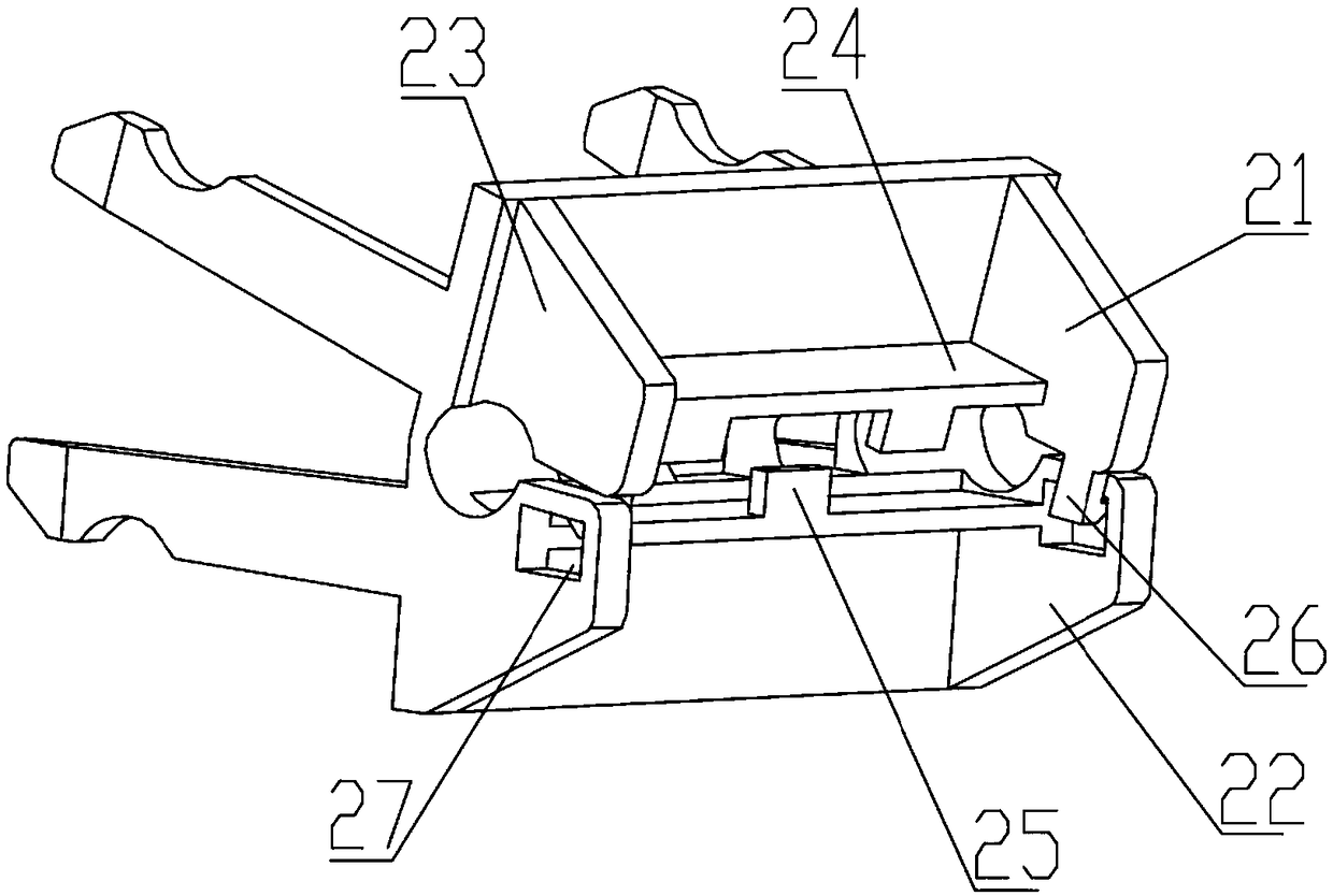
[0066] like Figure 7 and Figure 8 , Figure 7 It is a perspective view of the active state of the temperature control probe bracket in this embodiment; Figure 8 It is a perspective view of the temperature control probe bracket in a fixed state in this embodiment.

[0067] In this embodiment, the temperature control probe bracket includes a box body 4, the installation part 3 and the positioning part 2 are arranged on the box body 4, and the box body 4 includes a cover plate 41 and a bottom plate 42, The cover plate 41 and the bottom plate 42 are movably connected, and the cover plate 41 and the bottom plate 42 can freely rotate around the connecting position to realize the closing and closing between the cover plate 41 and the bottom plate 42 Open.

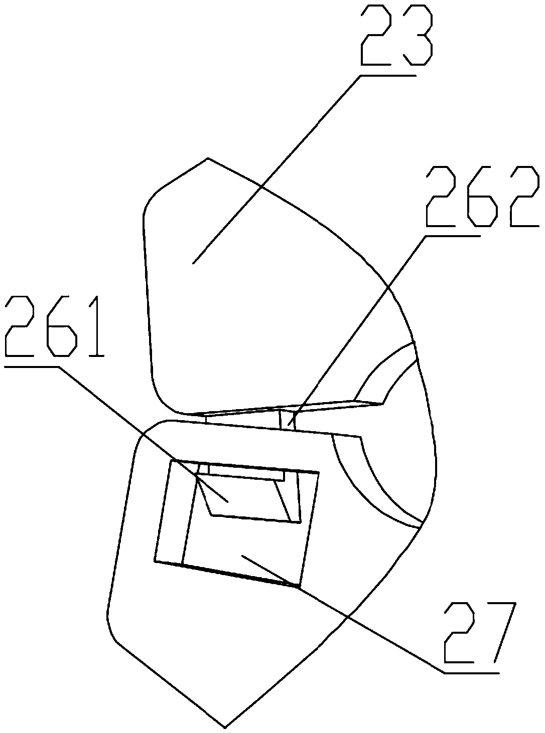
[0068] The locking block 26 and the locking slot 27 of the positioning portion 2 are respectively arranged on the cover plate 41 and the bottom plate 42 , and the locking block 26 and the locking slot 27 are correspondingly...


PUM


Abstract

The invention discloses a temperature-control probe support and an air conditioner. The temperature-control probe support comprises a clamping assembly and a mounting assembly. The mounting assembly comprises a positioning part and a mounting part. The positioning part is connected with the clamping assembly. The clamping assembly comprises a deformation part and a clamping part. The clamping assembly is fixed to a finned heat exchanger through deformation of the deformation part, and the deformation part can be kept in the deformed state through fixing by the positioning part, so that stableconnection of the clamping assembly and the finned heat exchanger is ensured. The mounting part is arranged on the clamping assembly and is used for mounting a temperature-control probe. By adoption of the temperature-control probe support of the structure, the temperature-control probe and the heat exchanger can be conveniently connected to be assembled or can be conveniently disassembled; and meanwhile, the clamping strength between the temperature-control probe support and the finned heat exchanger can be ensured, and the temperature-control probe support is unlikely to deform and fall whenimproperly stressed.

Description

technical field [0001] The invention relates to the field of air conditioning equipment, in particular to a temperature control probe bracket and an air conditioner. Background technique [0002] Air conditioners and similar products mainly use finned heat exchangers. Such products need to install the ambient temperature sensor on the surface of the finned heat exchanger to ensure the accuracy of ambient temperature measurement. The detachment of the ambient temperature sensor will affect the operation of the whole machine and product quality. At present, the ambient temperature sensor is generally fixed in the following way. The temperature control probe of the ambient temperature sensor is fixed in the plastic bracket, and then the special-shaped claw is set on the plastic bracket. On the copper tube of the finned heat exchanger, in order to achieve the purpose of fixing the ambient temperature temperature control probe and its plastic bracket on the side of the finned he...

Claims


Application Information

Patent Timeline
IPC IPC(8): F24F11/89F24F110/10
CPCF24F11/89F24F2110/10
Inventor 王传恒
Owner NINGBO AUX ELECTRIC
Why Eureka
Try Eureka