Thick electrode structure of lithium ion battery

A lithium-ion battery and electrode structure technology, applied in battery electrodes, non-aqueous electrolyte battery electrodes, structural parts, etc., can solve the problem of uneven distribution of conductive agents and pores, difficulty in infiltration of thick electrode electrolytes, and changes in the tortuosity of pole pieces. It can improve the rate and cycle performance, facilitate capacity development, and reduce EIS.

Pending Publication Date: 2021-12-03
TIANJIN ENERGIES
View PDF7 Cites 2 Cited by
  • Summary
  • Abstract
  • Description
  • Claims
  • Application Information

AI Technical Summary

Problems solved by technology

The single-porosity and pore-diameter structure electrode design increases the amount of single-layer coating, reduces the proportion of active materials, and adds porous channel conductive agent. The solvent floats up, which will easily lead to poor peeling force of the pole piece, uneven distribution of conductive agent and pores; in order to improve the energy density of the battery, from the perspective of increasing the surface density of the electrode, the coating amount of the electrode is increased, and the thickness of the electrode is increased. The tortuosity of the pores becomes larger, making it more difficult for the thick electrode electrolyte to infiltrate

Method used


Image

  • Thick electrode structure of lithium ion battery
  • Thick electrode structure of lithium ion battery
  • Thick electrode structure of lithium ion battery

Examples


Embodiment 1

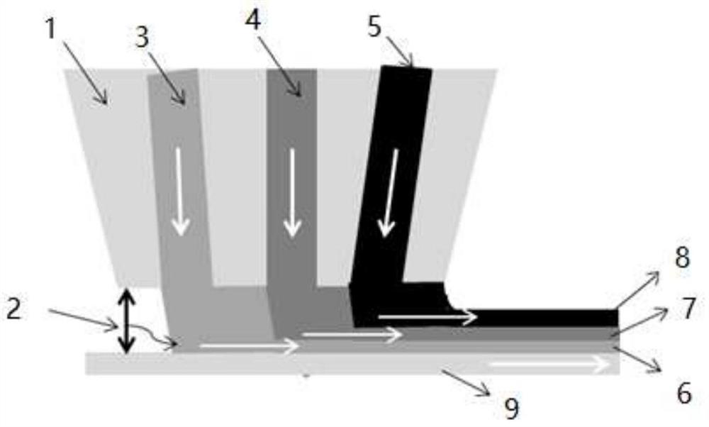
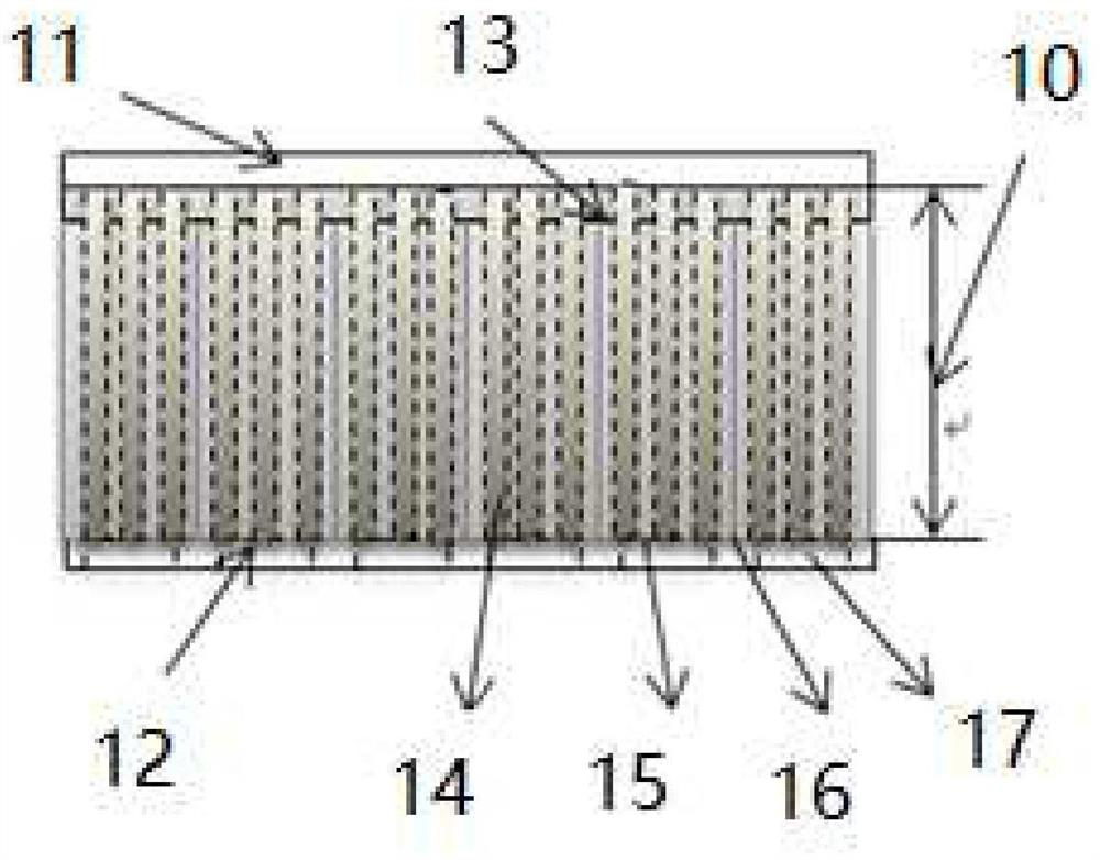
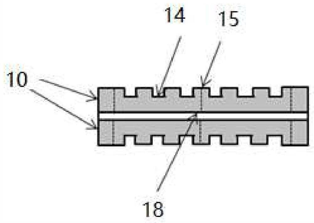
[0042] The negative electrode current collector 9 (the copper foil thickness is 8 um) is rolled, and the strip is formed, and the coating machine die 1 lip and the negative electrode current collector 9 are formed between the coating machine dielectric 9. The gap 2 (about 200um) between the mouth and the current body, three different components of the negative slurry from three cavities: No. 1 coating machine die cavity 3, No. 2 coating machine die cavity 4, three Number coater die cavity 5 lip extruded, the gap 2 between the coated machine dielectric slurry, the three-layer wet coating, three-stage porosity and The wet coating of the pore structure facilitates the infiltration of the electrolyte from the surface of the dressing layer 10 to the direction fluid 18, and improves the adhesion between the dressing layer 10 and the current collector 18, thereby improving the magnification and cycle performance of the thick electrode battery. Reduced lithium lithium risks under high-mag...

Embodiment 2

[0047] The negative electrode current collector 9 (the copper foil thickness is 8 um) is rolled, and the strip is formed, and the coating machine die 1 lip and the negative electrode current collector 9 are formed between the coating machine dielectric 9. The gap 2 (about 200um) between the mouth and the current body, three different components of the negative slurry from three cavities: No. 1 coating machine die cavity 3, No. 2 coating machine die cavity 4, three Number coater die cavity 5 lip extruded, the gap 2 between the coated machine dielectric slurry, the three-layer wet coating, three-stage porosity and The wet coating of the pore structure facilitates the infiltration of the electrolyte from the surface of the dressing layer 10 to the direction fluid 18, and improves the adhesion between the dressing layer 10 and the current collector 18, thereby improving the magnification and cycle performance of the thick electrode battery. Reduced lithium lithium risks under high-mag...

Embodiment 3

[0052] 9 the negative electrode collector (copper foil having a thickness of 8um) on the volume, threading, extruded backing roll coater, a die coater so that the lip 1 and the negative electrode collector is formed between the coater die lip 9 between the port and the collector slit (about 200um), three kinds of negative electrode slurry different components from three cavities: One coating machine body 3 of the die cavity, the die coater II cavities 4, three No. coater die cavity after extrusion lip 5, the gap between the coater die lip 2 and the current collector, to achieve three-wet coating, the porosity of three different components of the slurry and the negative electrode the wet coating pore structure facilitates infiltration of the electrolyte layer 10 from the surface of the dressing to the direction of the current collector 18, 10 and the dressing layer improves adhesion of the current collector 18, thereby improving the rate and cycle characteristics of the thick elect...


PUM

PropertyMeasurementUnit
thicknessaaaaaaaaaa

Abstract

The invention provides a thick electrode structure of a lithium ion battery. The thick electrode structure comprises a coating machine die head, and a gap between a coating die head lip and a current collector is formed between the coating machine die head and a negative current collector; the coating machine die head is provided with a plurality of coating machine die head cavities, and the cavities are not communicated with one another; negative electrode slurry with different components is extruded from a slit of the coating machine die head lip, so that negative electrode slurry with different components can be formed, the current collector is wet-coated with the negative electrode slurry with different components at the same time; two sides of a dressing layer of a rolled electrode roll are respectively provided with a non-tab side blank space and a tab side blank space, and electrode thickness direction grooves are arranged along an electrode thickness direction; groove gaps are formed between the electrode thickness direction grooves, and the electrode thickness direction grooves are formed in the surface of each electrode piece. According to the thick electrode structure of the lithium ion battery, the infiltration of electrolyte from the surface of the dressing layer to the current collector is facilitated, the binding power between the dressing layer and the current collector and the rate and cycle performance of the thick electrode battery are improved, and the lithium precipitation risk under high-rate charge and discharge is reduced.

Description

Technical field [0001] Technical Field The present invention pertains to the production of lithium-ion battery, particularly to a lithium ion battery electrode structure thickness. Background technique [0002] With the maturity of the development of lithium-ion battery technology, we continue to support the national policy for the development of new technology and promote the energy industry, new energy automotive industry demand for lithium-ion batteries high energy density, light weight and high power is increasing. The method of improving the current lithium ion battery energy density, one from the design point of view, to increase the volume of the electrical design space of the core structure, to increase the total amount of active substance; the second is the ratio of the design from the electrochemical point of view, to reduce non-active ingredients , increase the proportion of the active material in the electrode; third material system from the design point of view, redu...

Claims


Application Information

Patent Timeline
Patent Type & Authority Applications(China)
IPC IPC(8): H01M4/13H01M4/78H01M10/0525
CPCH01M4/13H01M4/78H01M10/0525H01M2004/021Y02E60/10
Inventor 陈素娜马华
Owner TIANJIN ENERGIES
Why Eureka
Try Eureka