Laser emitting structure of laser radar and laser radar

A technology of laser radar and laser emission, which is applied in the direction of radio wave measurement systems and instruments, can solve the problems that are difficult to further improve and meet the requirements of scanning accuracy and scanning density of unmanned vehicles, so as to improve safety and reliability, The effect of high vertical angle resolution and good scanning effect

Pending Publication Date: 2018-10-02
HANGZHOU OLE SYST CO LTD
View PDF0 Cites 1 Cited by
  • Summary
  • Abstract
  • Description
  • Claims
  • Application Information

AI Technical Summary

Problems solved by technology

Limited by the manufacturing process and manufacturing cost, it is difficult to further improve the vertical angle resolution of the existing lidar when it reaches a certain value, and it is difficult to meet the requirements of the development of unmanned vehicles for scanning accuracy and scanning density

Method used


Image

  • Laser emitting structure of laser radar and laser radar
  • Laser emitting structure of laser radar and laser radar
  • Laser emitting structure of laser radar and laser radar

Examples


Embodiment Construction

[0024] The advantages of the present invention will be further elaborated below in conjunction with the accompanying drawings and specific embodiments.

[0025] Reference will now be made in detail to the exemplary embodiments, examples of which are illustrated in the accompanying drawings. When the following description refers to the accompanying drawings, the same numerals in different drawings refer to the same or similar elements unless otherwise indicated. The implementations described in the following exemplary examples do not represent all implementations consistent with the present disclosure. Rather, they are merely examples of apparatuses and methods consistent with aspects of the present disclosure as recited in the appended claims.

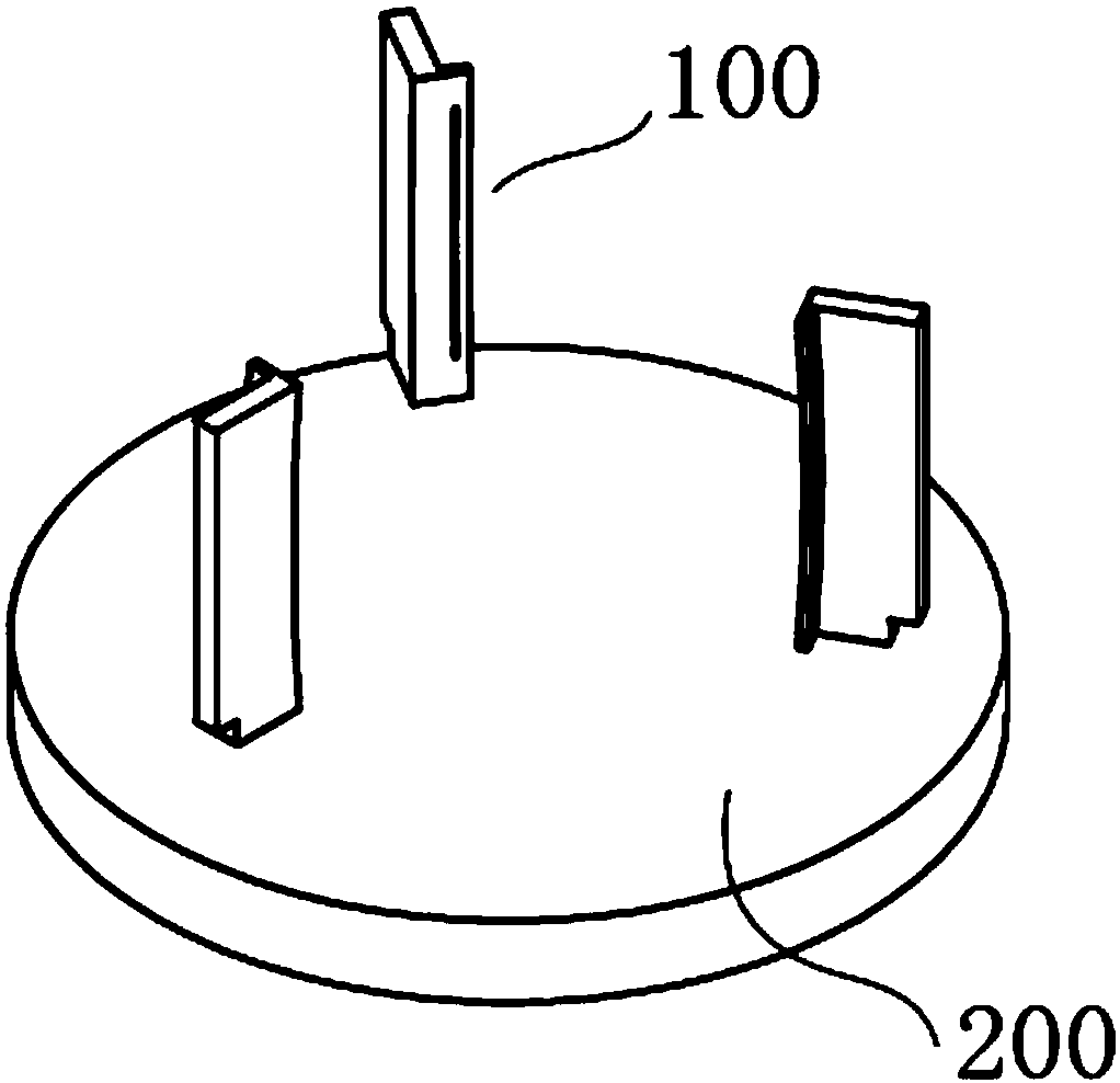
[0026] See attached figure 1 , the present invention discloses a laser emitting structure of a lidar, the emitting structure includes at least two emitting modules 100, the emitting modules 100 are fixedly arranged on the base 200 of...


PUM


Abstract

The invention provides a laser emitting structure of a laser radar and a laser radar. The emitting structure comprises at least two emitting modules; the emitting modules are fixedly arranged on a base of the laser radar, and the emitting modules are evenly distributed in the circumferential direction of the base; each emitting module has at least two emitting optical fibers, the emitting opticalfibers are evenly arranged on a vertical plane in the emitting module, extension lines of the emitting optical fibers intersect at the same point, and an included angle between the adjacent emitting optical fibers is alpha; the adjacent emitting modules are offset from each other in a vertical direction; the base rotates around its central axis, and the emitting optical fibers of different emitting modules pass through the same vertical plane, the mapped line segments formed on the vertical plane do not coincide with each other, and extension lines of the mapped line segments intersect at thesame point; and an included angle between the adjacent mapped line segments is less than alpha. The laser radar has the above laser emitting structure. After adopting the above technical solution, thelaser radar has higher vertical angle resolution, higher scanning precision and higher density.

Description

technical field [0001] The invention relates to the technical field of laser radar, in particular to a laser emitting structure of laser radar and a laser radar. Background technique [0002] LiDAR technology is widely used in navigation, map surveying, satellite positioning and other fields. In the field of autonomous driving, lidar plays a key role in map mapping and scene positioning. [0003] Today's unmanned vehicles mostly use mechanical laser radar (LiDAR). The so-called mechanical laser radar refers to the rotation of its transmitting system and receiving system in a macro sense. More accurate lasers change from "line" to "surface", and arrange multiple laser beams in the vertical direction to form multiple surfaces to achieve the purpose of dynamic 3D scanning and dynamic receiving of information. Vertically arranged laser emitters emit outwards at different angles to form multiple scanning lines to achieve vertical angle coverage, and at the same time, driven by ...

Claims


Application Information

Patent Timeline
IPC IPC(8): G01S7/481
CPCG01S7/4815
Inventor 张瓯曾庆胜牛青
Owner HANGZHOU OLE SYST CO LTD
Why Eureka
Try Eureka