Identifier definition method of user terminal, network side device and user terminal
A technology of network side equipment and user terminals, applied in the field of communication
- Summary
- Abstract
- Description
- Claims
- Application Information
AI Technical Summary
Problems solved by technology
Method used
Image

Examples
no. 1 example
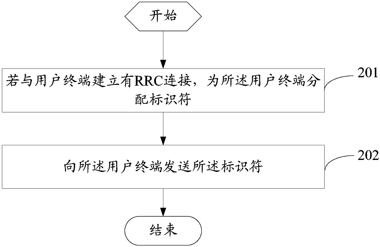
[0045] see figure 2 , figure 2 is a flowchart of a method for defining an identifier of a user terminal provided by an embodiment of the present invention, and the method is applied to a network side device, such as figure 2 shown, including the following steps:
[0046] Step 201: If an RRC connection is established with the user terminal, assign an identifier to the user terminal, wherein different user terminals in the notification area of the same network side are assigned different identifiers.
[0047]Wherein, the establishment of an RRC connection with the user terminal in this step can be understood as the process of establishing an RRC connection between the user terminal and the network-side device, or the user terminal and the network-side device have completed the RRC connection, or the network-side device releases the RRC connection with the user terminal. During the RRC connection process, that is, step 201 may be during the process of establishing an RRC c...
no. 2 example
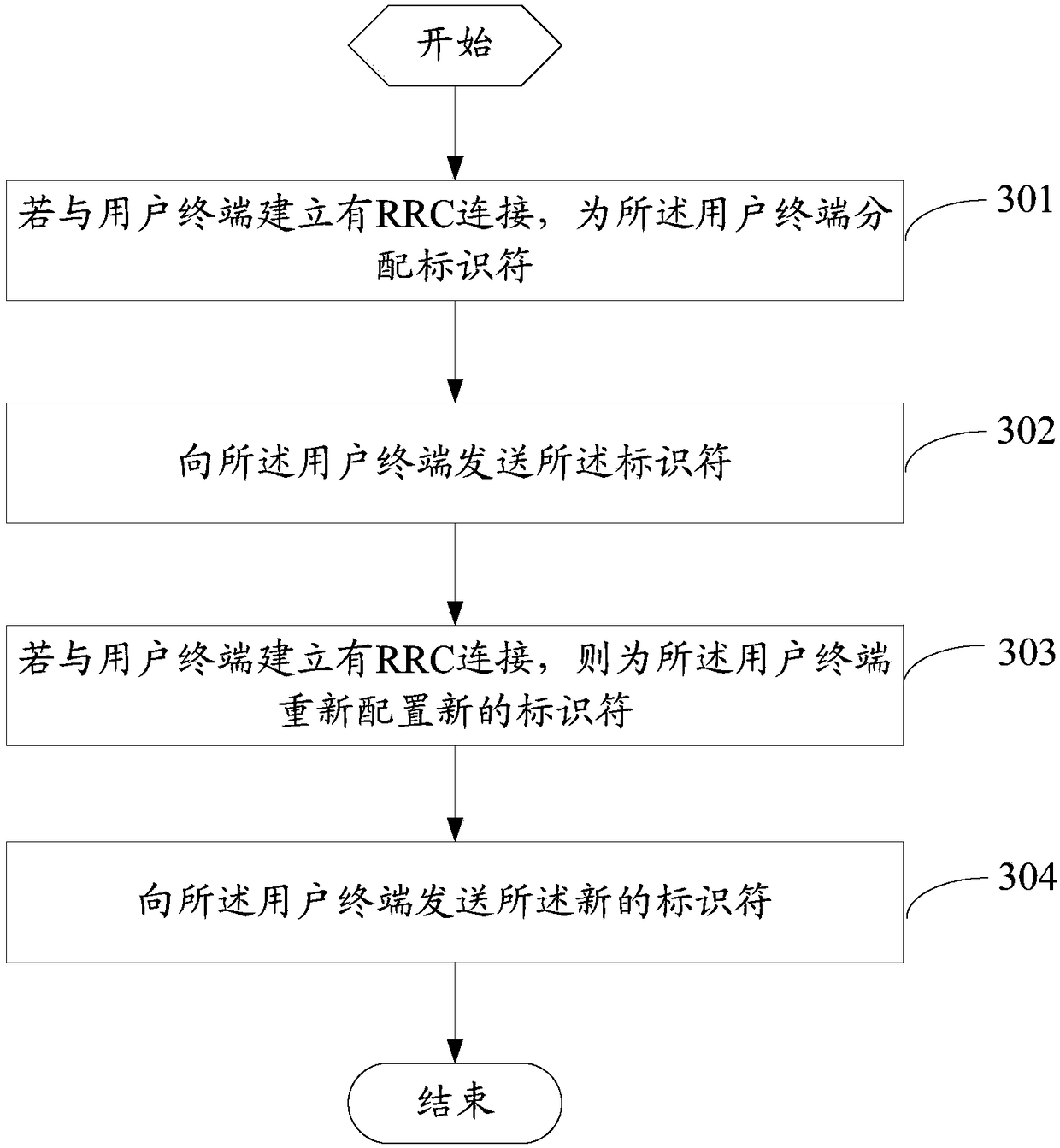
[0060] see image 3 , image 3 is a flowchart of a method for defining an identifier of a user terminal provided by an embodiment of the present invention, and the method is applied to a network side device, such as image 3 shown, including the following steps:
[0061] Step 301: If an RRC connection is established with the user terminal, assign an identifier to the user terminal, where different user terminals in the notification area on the same network side are assigned different identifiers.
[0062] Establishing an RRC connection with the user terminal in this step can be understood as the process of establishing an RRC connection between the user terminal and the network-side device, or the user terminal and the network-side device have completed the RRC connection, or the network-side device releases the RRC connection with the user terminal. During the connection process, that is, step 201 may be during the process of establishing an RRC connection between the user ...
no. 3 example
[0105] see Figure 4 , Figure 4 is a flowchart of a method for defining an identifier of a user terminal provided by an embodiment of the present invention, and the method is applied to a user terminal, such as Figure 4 shown, including the following steps:
[0106] Step 401, if the user terminal establishes an RRC connection with the network side equipment, receive the identifier sent by the network side equipment.
[0107] Wherein, for the above-mentioned identifier, reference may be made to the corresponding descriptions of the first embodiment and the second embodiment, which will not be repeated here, and the same beneficial effect may be achieved.
[0108] Step 402. Use the identifier when the user terminal is in an inactive state.
[0109] Wherein, the identifier is unique to all cells in the network-side notification area configured for the user terminal by the network side, and the identifier is used to identify the user terminal when the user terminal is in an i...
PUM
 Abstract
Description
Claims
Application Information
 - R&D
- Intellectual Property
- Life Sciences
- Materials
- Tech Scout
- Unparalleled Data Quality
- Higher Quality Content
- 60% Fewer Hallucinations
Browse by: Latest US Patents, China's latest patents, Technical Efficacy Thesaurus, Application Domain, Technology Topic, Popular Technical Reports.
© 2025 PatSnap. All rights reserved.Legal|Privacy policy|Modern Slavery Act Transparency Statement|Sitemap|About US| Contact US: help@patsnap.com