Solder joint structure, solder joint method and solder joint auxiliary tool

A bonding structure and bonding method technology, applied in the field of solder bonding aids, can solve the problem of low productivity and high

Active Publication Date: 2018-10-09
NIDEC CORP
View PDF12 Cites 0 Cited by
  • Summary
  • Abstract
  • Description
  • Claims
  • Application Information

AI Technical Summary

Problems solved by technology

Therefore, when the mounting member and the joined portion are bonded by solder, the productivity is not so high because the number of steps is increased in the method of holding the mounting member.

Method used


Image

  • Solder joint structure, solder joint method and solder joint auxiliary tool
  • Solder joint structure, solder joint method and solder joint auxiliary tool
  • Solder joint structure, solder joint method and solder joint auxiliary tool

Examples


Embodiment Construction

[0019] Hereinafter, embodiments of the present invention will be described in detail with reference to the drawings. In addition, the same code|symbol is attached|subjected to the same or corresponding part in a figure, and the description is not repeated. In addition, the dimensions of the components in the drawings do not represent the dimensions of the actual components, the dimensional ratios of the components, and the like.

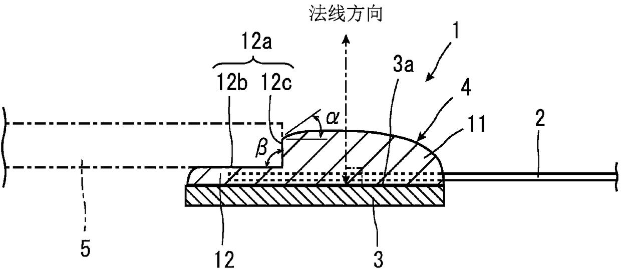
[0020] In addition, in the following description, the direction (normal direction) perpendicular|vertical to the surface 3a of the to-be-joined part 3 is called "up-down direction." And, the direction parallel to the surface 3 a of the joined portion 3 is referred to as "lateral direction".

[0021] (solder joint structure)

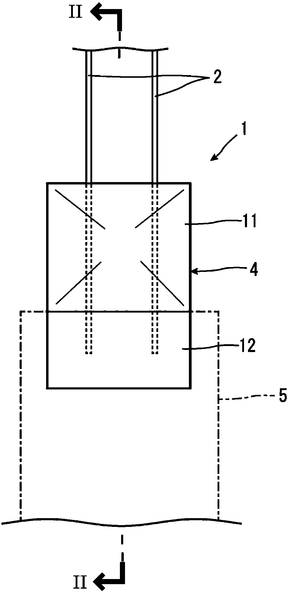
[0022] figure 1 It is a plan view schematically showing the solder joint structure 1 according to the embodiment of the present invention. figure 2 yes figure 1 The II-II line sectional view in. The solder joint structure...


PUM


Abstract

The invention provides a solder joint structure, a solder joint method and a solder joint auxiliary tool. The solder joint structure is a structure for bonding a mounting member that is long in one direction to the surface of an engaged portion using solder. The solder joint structure comprises a convex part which protrudes in a convex shape relative to the surface of the engaged portion; and a flat portion having a flat surface on at least a portion of the outer surface. When viewed in a cross-section perpendicular to the surface of the engaged portion, the upper end of the flat part is closer to the surface of the engaged portion than the upper end of the convex part. When viewed on a cross-section, under the condition that the surface of the engaged portion is taken as a reference, theslope of the outer surface of the convex part side in the flat part is larger than the slope of the outer surface of the flat part side in the convex part.

Description

technical field [0001] The present invention relates to a solder joint structure, a solder joint method, and an auxiliary tool for solder joint. Background technique [0002] As one of methods of joining components to each other, a solder joining method using solder is generally used. In the case where components are joined to each other using solder, it is necessary to melt the solder after supplying the solder to these joined portions. When the solder is melted, the flux contained in the solder forms bumps by heat when the solder is melted, or the molten solder is raised by surface tension. Therefore, in the case where the parts to be joined are long parts in one direction, there is a possibility that the parts are caused to move from the joining position by melting the solder. Therefore, it is necessary to hold the part long in the one direction until the joining with solder is completed. [0003] As a method of holding a member long in one direction as described above...

Claims


Application Information

Patent Timeline
IPC IPC(8): B23K26/244B23K26/70
CPCB23K26/244B23K26/70
Inventor 本田弘之西冈澄人佐斋一宏花野雅昭
Owner NIDEC CORP
Why Eureka
Try Eureka