Steel structure positioning and conveying construction frame

A construction frame and steel structure technology, which is applied in the direction of building construction, construction, and building material processing, can solve problems such as adjustment, angle adjustment, and potential safety hazards in I-beam transmission, and achieve the effect of increasing transmission accuracy

Active Publication Date: 2018-10-09
ZHIMAIDE CO LTD
View PDF6 Cites 14 Cited by
  • Summary
  • Abstract
  • Description
  • Claims
  • Application Information

AI Technical Summary

Problems solved by technology

[0004] In order to solve the above problems, the present invention provides a steel structure positioning transmission construction frame, which can solve the problem that the angle of the I-beam cannot be adjusted when the I-beam is transmitted to the installation position, and the I-beam cannot be adjusted when the I-beam is transmitted. All-round fixation of the I-beam, potential safety hazards in the transmission of the I-beam, and manual adjustment of the position of the I-beam when it is transported to the installation location; can achieve all-round fixation of the I-beam, and the I-beam The function of delivering the steel to the appropriate position, with the ability to adjust the angle of the I-beam when it is delivered to the installation position, and the I-beam can be fixed in all directions when the I-beam is delivered, there is no safety hazard in the I-beam transmission, When the steel is delivered to the installation position, its position is automatically adjusted, etc.

Method used


Image

  • Steel structure positioning and conveying construction frame
  • Steel structure positioning and conveying construction frame
  • Steel structure positioning and conveying construction frame

Examples


Embodiment Construction

[0024] In order to make the technical means, creative features, goals and effects achieved by the present invention easy to understand, the present invention will be further elaborated below in conjunction with specific illustrations. It should be noted that, in the case of no conflict, the embodiments in the present application and the features in the embodiments can be combined with each other.

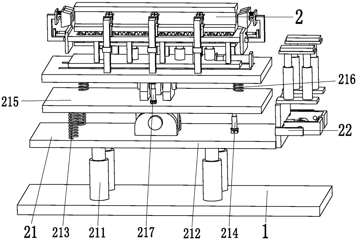
[0025] Such as Figure 1 to Figure 5 Shown, a kind of steel structure positioning conveys construction frame, comprises supporting base plate 1 and lifting device 2, and lifting device 2 is installed on the top of described supporting base plate 1.

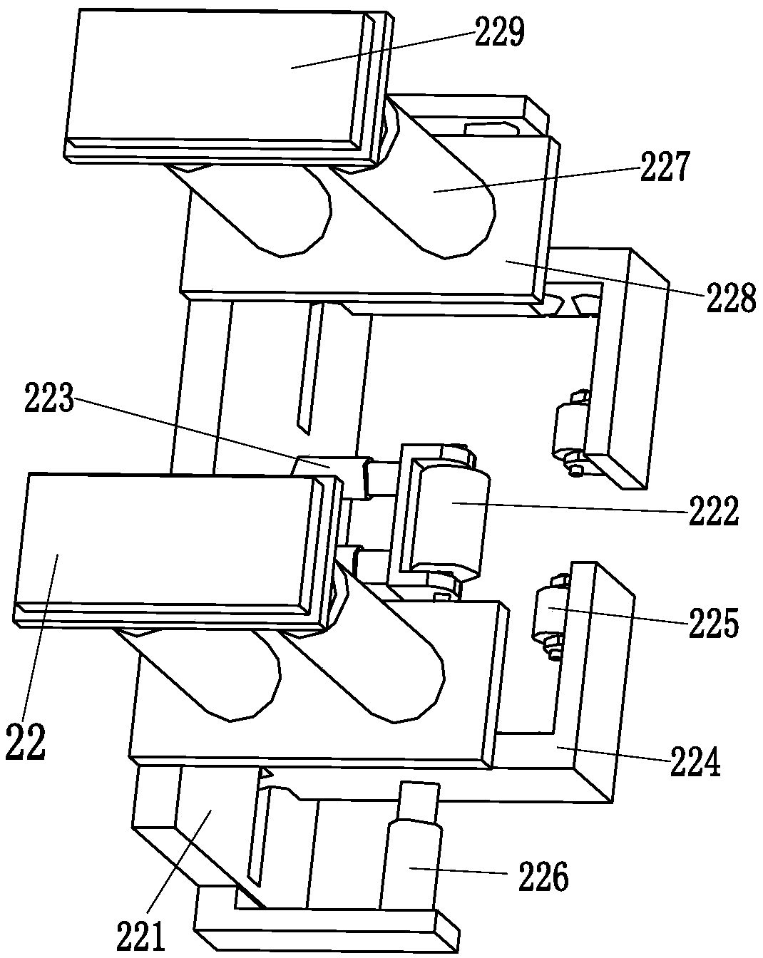
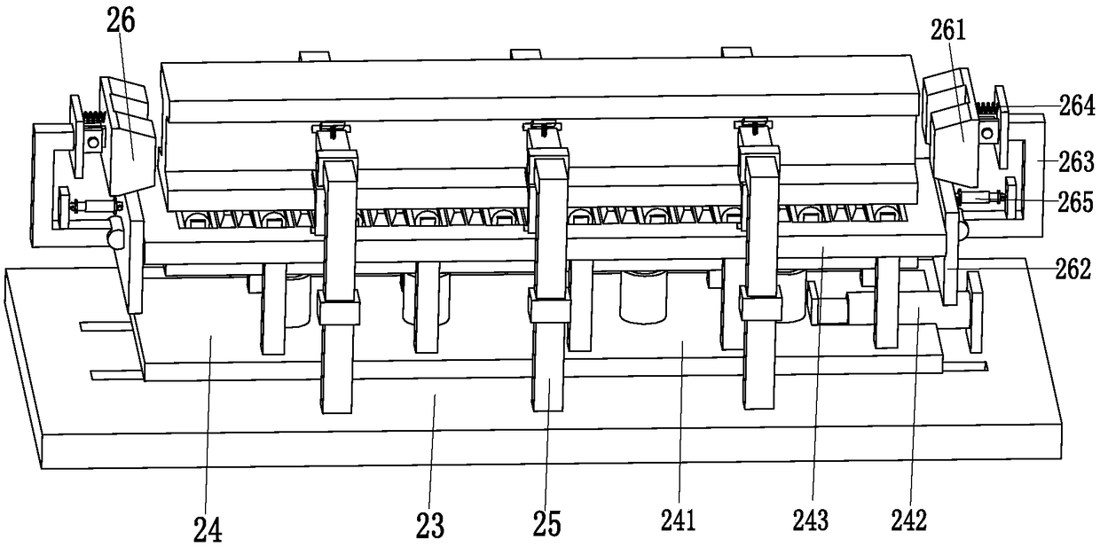
[0026] The lifting device 2 includes a lifting adjustment mechanism 21, a limit mechanism 22, a fixed base plate 23, a locking mechanism 24, a side fixed branch chain 25 and a locking mechanism 26, and the lifting adjustment mechanism 21 is installed on the top of the supporting base plate 1. A fixed bottom plate 23 is installed on the...


PUM


Abstract

The invention relates to a steel structure positioning and conveying construction frame comprising a supporting bottom plate and a lifting device. The lifting device is mounted at the top of the supporting bottom plate and comprises a lifting adjustment mechanism, a limiting mechanism, a fixing bottom plate, a locking mechanism, side fixing branch chains and position clamping mechanisms; and the locking mechanism comprises a locking sliding plate, a locking pushing rod, a locking supporting frame, a locking hydraulic cylinder, a locking connecting plate, idler wheel frames, supporting idler wheels, locking clamping frames and clamping frame adjustment rods. According to the steel structure positioning and conveying construction frame, the problems that during conveying of existing I-shapedsteel, when the I-shaped steel is conveyed to the mounting position, the angle of the I-shaped steel cannot be adjusted, the I-shaped steel cannot be fixed in all directions during conveying of the I-shaped steel, security hidden dangers exist during conveying of the I-shaped steel, and the position of the I-shaped steel needs to be adjusted manually when the I-shaped steel is conveyed to the mounting position can be solved; and the functions that the I-shaped steel can be fixed in all directions and the I-shaped steel is conveyed to the proper position can be achieved.

Description

technical field [0001] The invention relates to the technical field of building steel structures, in particular to a steel structure positioning transmission construction frame. Background technique [0002] Steel structure is a structure composed of steel materials, which is one of the main types of building structures. The structure is mainly composed of steel beams, steel columns, steel trusses and other components made of section steel and steel plates. It is simple and widely used in large-scale workshops, venues, super high-rises and other fields; steel structure pillars and cross columns need to be built first during steel structure construction. I-beams are erected and installed on the column. Because different designs require I-beams to be installed with a certain inclination angle, or I-beams need to be installed in staggered positions, this will bring many difficulties to the transmission of I-beams. [0003] The transmission of I-beams is generally completed by ...

Claims


Application Information

Patent Timeline
Patent Type & Authority Applications(China)
IPC IPC(8): E04G21/16
CPCE04G21/162
Inventor 莫小雨
Owner ZHIMAIDE CO LTD
Why Eureka
Try Eureka