High-rigidity plate and air-conditioning apparatus
A high-rigidity, top-wall technology, used in air-conditioning systems, mechanical equipment, lighting and heating equipment, etc., can solve the problems of large wall vibration and low rigidity, and achieve the effect of enhancing rigidity
- Summary
- Abstract
- Description
- Claims
- Application Information
AI Technical Summary
Problems solved by technology
Method used
Image

Examples
Embodiment Construction
[0015] Exemplary embodiments of the present invention are disclosed below. The configuration of the embodiment described below and the operations and effects achieved by the configuration are merely exemplary. The invention may be practiced using configurations other than those disclosed herein. In addition, the present invention can achieve at least one of various effects (including secondary effects) obtained by this configuration.
[0016] In each drawing, directions are defined for convenience. The X direction, the Y direction, and the Z direction intersect each other. In this specification, serial numbers are used to distinguish parts or components from one another, and do not indicate an order or preference.
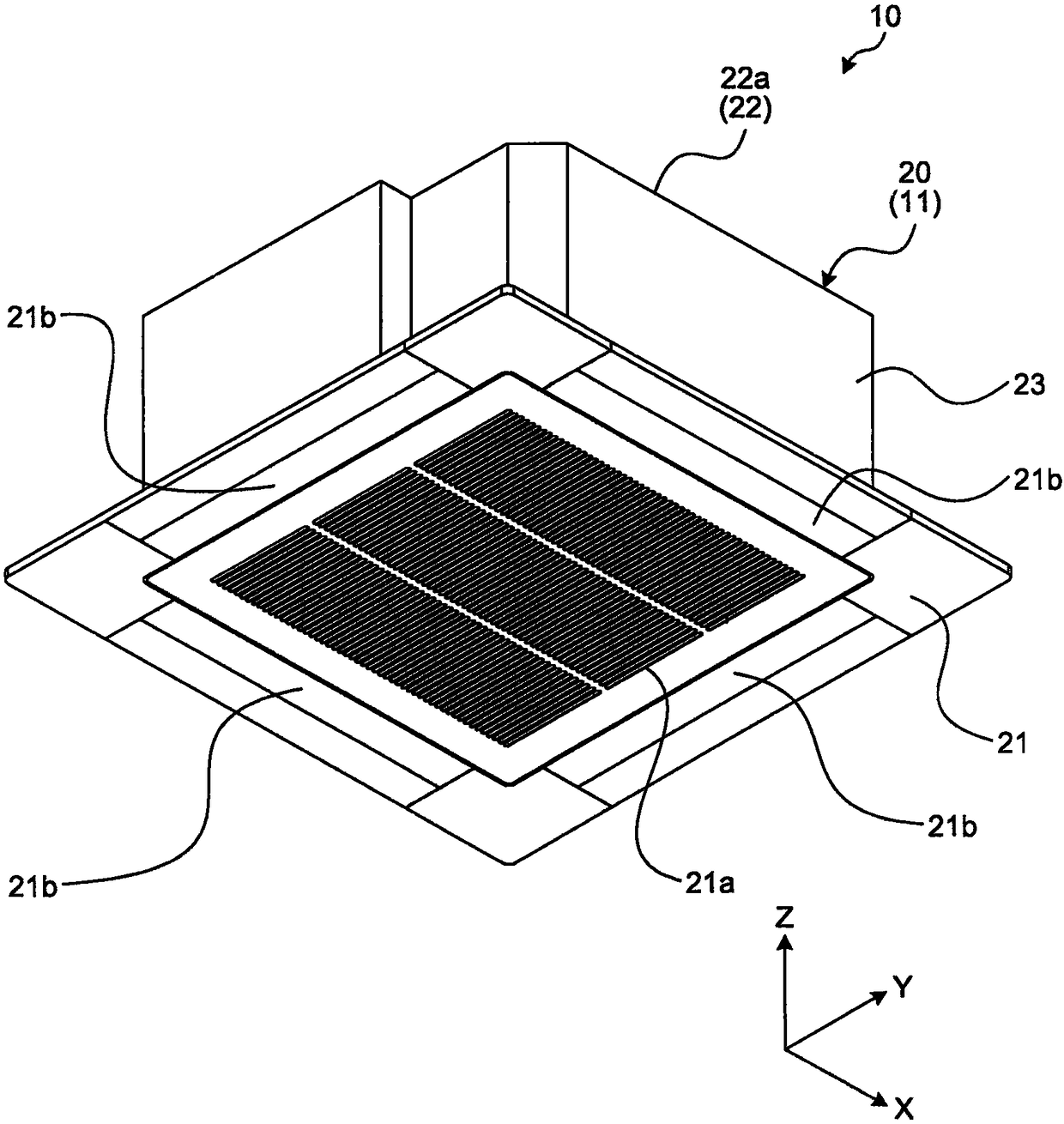
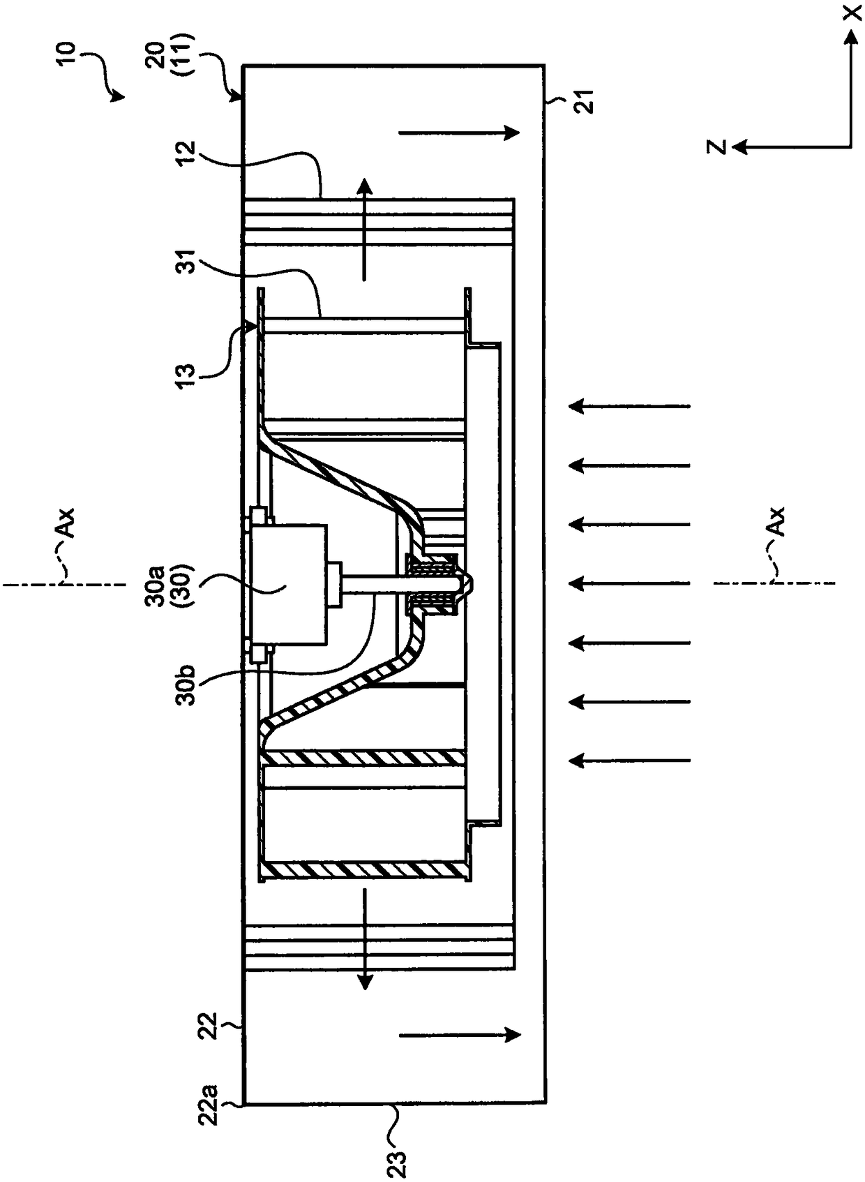
[0017] figure 1 is an exemplary schematic perspective view of the air-conditioning apparatus 10 in the embodiment. figure 2 is an exemplary schematic cross-sectional view of the air-conditioning apparatus 10 in the embodiment.
[0018] figure 1 and figure...
PUM
 Abstract
Description
Claims
Application Information
 - Generate Ideas
- Intellectual Property
- Life Sciences
- Materials
- Tech Scout
- Unparalleled Data Quality
- Higher Quality Content
- 60% Fewer Hallucinations
Browse by: Latest US Patents, China's latest patents, Technical Efficacy Thesaurus, Application Domain, Technology Topic, Popular Technical Reports.
© 2025 PatSnap. All rights reserved.Legal|Privacy policy|Modern Slavery Act Transparency Statement|Sitemap|About US| Contact US: help@patsnap.com