A Design Method for Pantograph Bow Head with Small Rotation Angle

A design method and pantograph technology, applied in design optimization/simulation, current collectors, electric vehicles, etc., can solve problems such as long calculation and analysis process cycle, long design cycle, topology change, etc., and achieve simple modification or addition of parameters. Efficient, reduce pantograph and catenary damage, optimize and solve fast results

Active Publication Date: 2021-09-17
ZHUZHOU ELECTRIC LOCOMOTIVE CO LTD
View PDF6 Cites 0 Cited by
  • Summary
  • Abstract
  • Description
  • Claims
  • Application Information

AI Technical Summary

Problems solved by technology

[0005] from image 3 It can be seen from the figure that there are many parameters, which must include the parameters of the main structure. The equations contain nonlinear functions such as sine, cosine, and tangent. completely changed structure
The entire calculation and analysis process has a long cycle, the equation group solution algorithm and optimization algorithm are inefficient, and the algorithm is unstable. When the distance limit of the initial condition of the pantograph is large, it is difficult to obtain the structural optimization solution quickly and efficiently, especially when there are many When the design variables are relatively strict or the relevant constraints such as the size of the main structure are relatively strict, it is not possible to obtain the optimal solution of the structure
[0006] In this way, more balance bars must be added to meet the requirements of the bow head rotation angle and reduce the restrictions on the main structure of the pantograph, so the topological structure and solution algorithm of the degree are completely changed, and the difficulty of programming and debugging is greatly increased. , the design cycle is long, most of the time is spent on programming and algorithms, and there is little performance analysis of the pantograph itself

Method used


Image

  • A Design Method for Pantograph Bow Head with Small Rotation Angle
  • A Design Method for Pantograph Bow Head with Small Rotation Angle
  • A Design Method for Pantograph Bow Head with Small Rotation Angle

Examples


Embodiment Construction

[0033] The specific optimization steps of the present invention are as follows:

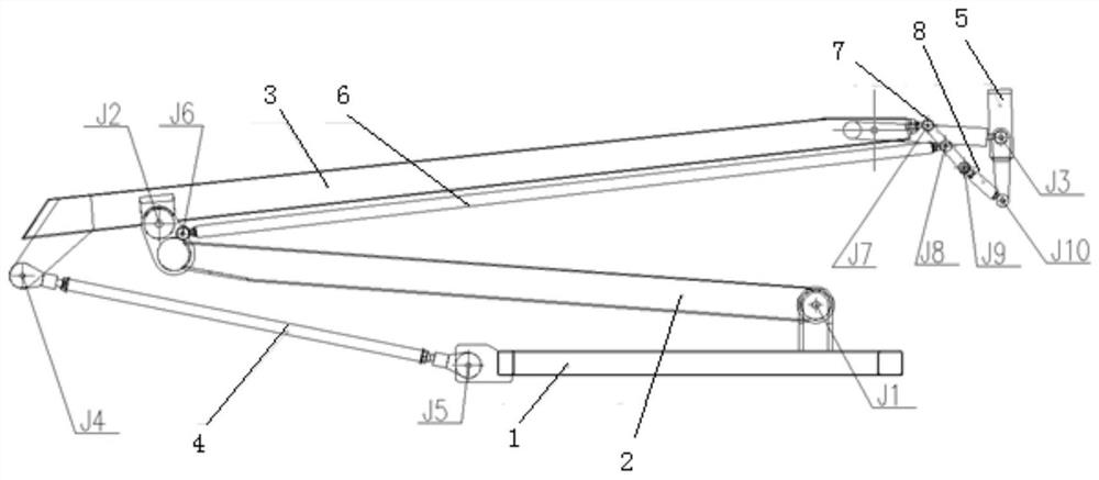
[0034] (1) Establish a non-parametric pantograph dynamics model in general dynamics software (such as SIMPACK, RECURDYN, ADAMS, etc.) according to the pantograph design scheme. On the basis of the initial graphic geometry of existing 3D CAD software (such as UG, etc.), taking the pantograph scheme in Figure 1 as an example, the process of establishing a non-parametric pantograph dynamics model is explained.

[0035] Establish the parts and geometry of the non-parametric pantograph dynamic model, input the three-dimensional geometry of each part 1-8 in the dynamic software in turn, if a part is composed of several parts, merge this part in the dynamic software The parts form the same Part (software term), the software will select the material of the part as steel by default, you can choose the material in the software library or directly assign the weight to the part, the software will automatical...


PUM


Abstract

The invention discloses a design method for a pantograph head with a small rotation angle. The method uses the relative position parameter coordinates of the hinge point of the pantograph, and utilizes mature dynamics software and an integrated general optimization algorithm library to optimize the rotation angle of the bow head. The deflection angle of the pantograph head is significantly reduced, the bow head is almost in a translational state within the working range of the lifting bow, and the contact area between the pantograph and the catenary is increased, which effectively improves the pantograph The flow quality reduces pantograph-catenary damage.

Description

technical field [0001] The invention relates to the technical field of rail vehicle pantographs, in particular to a design method for a pantograph head with a small rotation angle. Background technique [0002] When the single carbon sliding plate is in contact with the catenary to receive current, the contact area is easily affected by the relative angle between the carbon sliding plate of the pantograph head and the contact line of the catenary. Since the catenary is a stationary device and the vehicle is a mobile device, the vertical height of the contact line of the catenary relative to the vehicle changes during the movement of the vehicle, which causes the working height of the pantograph to change, thereby causing the carbon slide to be opposite to the contact line. Angle changes. When the deflection angle of the bow head carbon skateboard is large, the contact between the single carbon skateboard and the catenary changes from line contact to point contact, and the c...

Claims


Application Information

Patent Timeline
Patent Type & Authority Patents(China)
IPC IPC(8): G06F30/20B60L5/18
CPCB60L5/18G06F30/20
Inventor 袁文辉王先锋蒋忠城张彦林冯叶陈敏坚
Owner ZHUZHOU ELECTRIC LOCOMOTIVE CO LTD
Why Eureka
Try Eureka