Electric braking compensation control method, controller, electric power-assisting auxiliary system and automobile
A technology of compensation control and electric power assist, applied in the direction of brakes, brake transmission devices, vehicle components, etc., can solve the problems affecting the driving comfort of the driver, the impact of vehicle braking, and the inability to meet the needs of vehicle braking torque, etc., to achieve Improve driving mileage and braking efficiency, avoid deceleration reduction, and ensure vehicle safety
Active Publication Date: 2018-10-12
BEIJING ELECTRIC VEHICLE
5 Cites 3 Cited by
AI-Extracted Technical Summary
Problems solved by technology
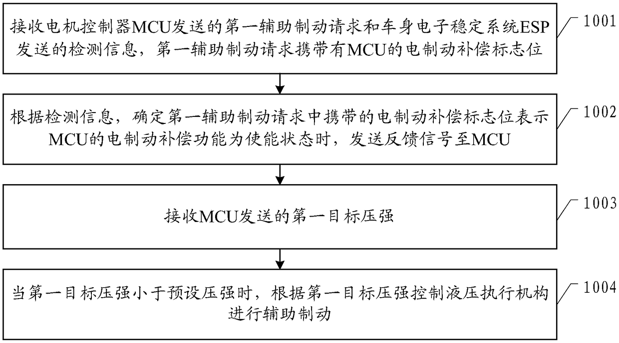
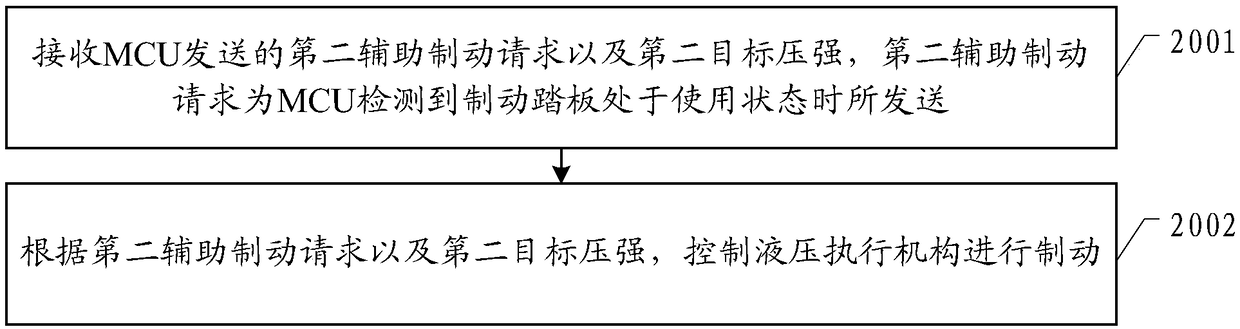
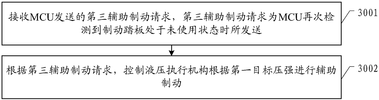
[0003] The technical problem to be solved by the embodiments of the present invention is to provide an electric brake compensation control method, a controller, an electric power assist auxiliary system, and an automobile to solve the problem that the cur...
Method used
[0141] In an embodiment of the present invention, an electric power assist auxiliary system 1 is provided, including a hydraulic actuator and the controller 11 as described above; the controller 11 judges whether to control the hydraulic actuator 12 according to the received information Auxiliary braking and the pressure of the hydraulic actuator when performing auxiliary braking. When the electri...
Abstract
The embodiment of the invention provides an electric braking compensation control method, a controller, an electric power-assisting auxiliary system and an automobile. The electric braking compensation control method comprises the steps that a first auxiliary braking request sent by a motor control unit (MCU) and detecting information sent by an automobile body electronic stability program (ESP) are received; according to the detecting information, when the situation that an electric braking compensation zone bit carried in the first auxiliary braking request represents that the electric braking compensation function of the MCU is in an enabling state is determined, a feedback signal is sent to the MCU; the first target pressure intensity sent by the MCU is received; and when the first target pressure intensity is less than the preset pressure intensity, a hydraulic actuating mechanism is controlled to conduct auxiliary braking according to the first target pressure intensity. The electric power-assisting auxiliary system in the scheme can provide auxiliary braking for electric braking when the situation that electric braking is in an unexpected weakening state is judged accordingto the information provided by the MCU and the ESP, it is ensured that the braking torque is within the normal braking range, and meanwhile, the influence on the driving comfort of a driver is avoided.
Application Domain
Braking action transmission
Technology Topic
Driver/operatorBrake torque +6
Image
Examples
- Experimental program(1)
Example Embodiment
[0069] In order to make the technical problems, technical solutions and advantages to be solved by the present invention clearer, a detailed description will be given below in conjunction with the accompanying drawings and specific embodiments. In the following description, specific details such as specific configurations and components are provided only to help a comprehensive understanding of the embodiments of the present invention. Therefore, it should be clear to those skilled in the art that various changes and modifications can be made to the embodiments described herein without departing from the scope and spirit of the present invention. In addition, for clarity and conciseness, descriptions of known functions and configurations are omitted.
[0070] It should be understood that "one embodiment" or "an embodiment" mentioned throughout the specification means that a specific feature, structure, or characteristic related to the embodiment is included in at least one embodiment of the present invention. Therefore, the appearances of "in one embodiment" or "in an embodiment" in various places throughout the specification do not necessarily refer to the same embodiment. In addition, these specific features, structures, or characteristics can be combined in one or more embodiments in any suitable manner.
[0071] In various embodiments of the present invention, it should be understood that the size of the sequence number of the following processes does not mean the order of execution. The execution order of each process should be determined by its function and internal logic, and should not be implemented in the present invention. The implementation process of the example constitutes any limitation.
[0072] It should be understood that the term "and/or" in this text is only an association relationship describing the associated objects, which means that there can be three relationships, for example, A and/or B can mean that there is A alone, and both A and B exist. , There are three cases of B alone. In addition, the character "/" in this text generally indicates that the associated objects before and after are in an "or" relationship.
[0073] In the embodiments provided in this application, it should be understood that "B corresponding to A" means that B is associated with A, and B can be determined according to A. However, it should also be understood that determining B based on A does not mean that B is determined only based on A, and B can also be determined based on A and/or other information.
[0074] See figure 1 A preferred embodiment of the present invention provides an electric brake compensation control method, which is applied to an electric power assist system, including:
[0075] Step 1001, receiving the first auxiliary braking request sent by the motor controller MCU and the detection information sent by the body electronic stability system ESP, the first auxiliary braking request carrying the MCU electric braking compensation flag;
[0076] Step 1002: According to the detection information, it is determined that the electric brake compensation flag carried in the first auxiliary brake request indicates that the electric brake compensation function of the MCU is in the enabled state, and a feedback signal is sent to the MCU;
[0077] Step 1003: Receive the first target pressure sent by the MCU;
[0078] Step 1004: When the first target pressure is less than the preset pressure, the hydraulic actuator is controlled to perform auxiliary braking according to the first target pressure.
[0079] In the embodiment of the present invention, when the electric braking compensation function is enabled, the electric power assist system controls the hydraulic actuator to perform auxiliary braking according to the first target pressure sent by the motor controller MCU, so that the electric braking capability When it is unexpectedly weakened, the auxiliary braking of the hydraulic actuator is used to ensure that the braking torque is within the normal braking range to ensure the safety of the vehicle, and then through the sliding energy recovery to increase the driving range and braking efficiency, while avoiding vehicle braking The deceleration of the motor is reduced, and the impact on the driver’s driving comfort.
[0080] The preset pressure is a criterion for judging whether to control the hydraulic actuator to perform auxiliary braking based on functional safety, that is, when the first pressure is stronger than the preset pressure, it is safe to determine the first pressure to be an unreliable value or to perform auxiliary braking according to the first pressure Risk, the hydraulic actuator will not be controlled to perform auxiliary braking at this time; the preset pressure is mainly determined based on parameters including the maximum pressure or maximum braking torque that the hydraulic actuator can provide. In this embodiment, the preset pressure It is set to 20bar. In actual production, the appropriate preset pressure is determined according to the difference of the parts of the vehicle, which is used as a standard for controlling the actuator to perform auxiliary braking, and it belongs to the protection scope of the present invention.
[0081] Specifically, in the electric brake compensation control method as described above, the detection information includes: vehicle status information, gear information, status information of the vehicle stability control system, electronic parking brake system information, status information of the hydraulic actuator, and Information on the supply and demand of braking torque;
[0082] Among them, the vehicle stability control system includes at least one of the anti-lock braking system ABS, ESP, and the automatic braking system AEB.
[0083] In the embodiment of the present invention, the detection information sent by the ESP includes: vehicle status information, gear information, status information of the vehicle stability control system, and status information of the electronic parking brake system, used to determine whether the vehicle is in coasting energy Recycling status. The vehicle stability control system includes at least one of ABS, ESP, and AEB. Preferably, the state information of the vehicle stability control system is state information of all systems installed on the vehicle for vehicle stability control. In actual production, it is set according to the type of vehicle stability control system actually installed on the vehicle, including but not limited to ABS, ESP and AEB.
[0084] The detection information also includes: status information of the hydraulic actuator, which is used to determine whether the hydraulic actuator can operate normally.
[0085] The detection information also includes: braking torque supply and demand relationship information, which is used to determine whether the electric braking capacity of the vehicle meets the braking torque requirements in the coasting energy recovery state, and then determine whether it is necessary to start the hydraulic actuator.
[0086] Specifically, in the electric brake compensation control method as described above, when the electric brake compensation function of the MCU is in the enabled state, it includes: the vehicle is in the running state, the gear information is the forward gear, and the vehicle stability control system is in the off state. Active state, the electronic parking brake system is not activated, the accelerator pedal and the brake pedal are not in use, the difference between the braking torque demand value and the braking torque supply value is greater than the preset value, and the hydraulic actuator is in a trouble-free state At least one of them.
[0087] Preferably, in the embodiment of the present invention, when the electric brake compensation function of the MCU is in the enabled state, all the above restrictions are included to ensure that the vehicle is in a normal coasting energy recovery state and the electric power assist system can operate normally . Among them, the preset value is determined by technicians based on factors including the braking effect of electric brakes. In this embodiment, the preset value is set to 2NM. In actual production, it is determined according to the differences in the parts of the vehicle. Determining a suitable preset value for use as a criterion for controlling the actuator to perform auxiliary braking falls within the protection scope of the present invention. Optionally, adopting one or more of the above restriction conditions as a condition for judging that the vehicle is in a normal coasting energy recovery state also belongs to the protection scope of the present invention.
[0088] Specifically, in the electric brake compensation control method described above, the first target pressure is:
[0089] P 1 =R b1 *C=(R T -M)*C
[0090] Where P 1 Is the first target pressure;
[0091] R b1 Is the first required hydraulic braking torque;
[0092] R T Demand braking torque for coasting energy recovery;
[0093] M is the maximum supply braking torque of electric brake;
[0094] C is the conversion coefficient between pressure and braking torque.
[0095] In the embodiment of the present invention, the first target pressure is obtained by conversion of the first required hydraulic braking torque, and the first required hydraulic braking torque is the coasting energy recovery required braking torque and the electric braking maximum supply braking torque Difference.
[0096] See figure 2 Preferably, the electric brake compensation control method as described above, after the step of controlling the hydraulic actuator to perform braking according to the first target pressure, further includes:
[0097] Step 2001, receiving a second auxiliary braking request and a second target pressure sent by the MCU, where the second auxiliary braking request is sent when the MCU detects that the brake pedal is in use;
[0098] Step 2002, controlling the hydraulic actuator to perform braking according to the second auxiliary braking request and the second target pressure.
[0099] When the vehicle is in the auxiliary braking under the coasting energy state, the brake pedal is used, that is, the coasting mode is changed to the braking mode. If the electric brake compensation is directly exited at this time, the force provided by the hydraulic actuator suddenly disappears , It will affect the braking process of the whole vehicle, easily produce bumps, and then affect the driver's driving comfort. At this time, in the embodiment of the present invention, the electric power assist system receives the second auxiliary braking request and the second target pressure sent by the MCU according to the information of using the brake pedal in the coasting energy recovery state, and according to the second auxiliary The braking request and the second target pressure control the hydraulic actuator to brake, so that the electric brake compensation function continues to work. On the basis of ensuring the braking effect, only a part of the braking torque is increased, which affects the braking process of the whole vehicle. The impact is small, which helps ensure the driver's driving comfort.
[0100] Specifically, in the above-mentioned electric brake compensation control method, the second target pressure is:
[0101] P 2 =R b2 *C=(R T +R br -M)*C
[0102] Where P 2 Is the second target pressure;
[0103] R b2 Is the second required hydraulic braking torque;
[0104] R T Demand braking torque for coasting energy recovery;
[0105] R br Braking torque required for the pedal;
[0106] M is the maximum supply braking torque of electric brake;
[0107] C is the conversion coefficient between pressure and braking torque.
[0108] In the embodiment of the present invention, the second target pressure is obtained by conversion of the second required hydraulic braking torque, and the second required hydraulic braking torque includes the coasting energy recovery required braking torque and the pedal required braking torque The difference between the total required braking torque and the maximum supplied braking torque of the electric brake.
[0109] See image 3 Preferably, after the step of controlling the hydraulic actuator to perform auxiliary braking according to the second auxiliary braking request and the second target pressure, the electric brake compensation control method described above further includes:
[0110] Step 3001: Receive a third auxiliary braking request sent by the MCU, where the third auxiliary braking request is sent when the MCU detects that the brake pedal is in an unused state again;
[0111] Step 3002: According to the third auxiliary braking request, control the hydraulic actuator to perform auxiliary braking according to the first target pressure.
[0112] In the embodiment of the present invention, when the vehicle is in auxiliary braking under the braking condition, the MCU detects that the brake pedal is not in use again, that is, the user releases the brake pedal, and the vehicle changes from the braking condition to Coasting conditions, at this time the electric power assist system receives the third auxiliary braking request sent by the MCU, and controls the hydraulic actuator to perform auxiliary braking according to the first target pressure, ensuring that the braking torque is reduced and the coasting conditions are guaranteed Normal operation improves the driving range of the vehicle.
[0113] See Figure 4 Preferably, the electric brake compensation control method as described above further includes:
[0114] Step 4001: Receive the auxiliary brake exit signal sent by the MCU, where the auxiliary brake exit signal is sent when the MCU is in the first state;
[0115] Step 4002, according to the auxiliary brake exit signal, control the hydraulic actuator to exit the auxiliary brake.
[0116] In the embodiment of the present invention, when the auxiliary brake exit signal sent by the MCU is received, it indicates that there is a certain safety risk in continuing to perform the auxiliary brake or the vehicle does not need to be braked. At this time, the electric power assist system controls the hydraulic actuator Withdrawing from auxiliary braking will help reduce safety risks and ensure normal driving and driving safety of the vehicle.
[0117] Specifically, in the electric brake compensation control method described above, the first state includes:
[0118] The bus voltage of the MCU is greater than the preset voltage;
[0119] Or, the vehicle stability control system intervenes in braking;
[0120] Or, the vehicle stability control system malfunctions or the electronic parking brake system malfunctions.
[0121] In the embodiment of the present invention, the first state the MCU is in includes that the bus voltage of the MCU is greater than the preset voltage; or, the vehicle stability control system intervenes in braking; or, the vehicle stability control system fails or the electronic parking brake system error. When the MCU is in the first state, it indicates that there is a certain safety risk in continuing to perform the auxiliary braking. At this time, the auxiliary braking should be exited to reduce the safety risk; in addition to the above conditions, if other conditions are detected that affect the normal driving safety of the vehicle or the vehicle is not Conditions that require braking, such as the accelerator pedal being in use, the feedback power of the battery management system being greater than the preset power, or the total voltage of the battery management system being too high, as conditions for the MCU to be in the first state also fall within the protection scope of the present invention.
[0122] When the bus voltage of the MCU is greater than the preset voltage, the electric brake is prohibited. Therefore, the auxiliary brake used as electric brake compensation should also be withdrawn. The preset voltage is determined by the technician according to the actual MCU and its bus voltage capacity. There are no specific restrictions here.
[0123] When the vehicle stability control system intervenes in braking, the existence of auxiliary braking may affect the operation of the vehicle stability control system. At this time, exiting the auxiliary braking will help ensure the normal operation of the vehicle stability control system.
[0124] See Figure 5 , Another preferred embodiment of the present invention also provides a controller, which is applied to an electric assist assist system, including:
[0125] The first receiving module 501 is configured to receive the first auxiliary braking request sent by the motor controller MCU and the detection information sent by the body electronic stability system ESP, and the first auxiliary braking request carries the electric brake compensation flag bit of the MCU;
[0126] The processing module 502 is configured to, according to the detection information, determine that the electric brake compensation flag carried in the first auxiliary brake request indicates that the electric brake compensation function of the MCU is in the enabled state, and send a feedback signal to the MCU;
[0127] The second receiving module 503 is configured to receive the first target pressure sent by the MCU;
[0128] The first control module 504 is configured to control the hydraulic actuator to perform auxiliary braking according to the first target pressure when the first target pressure is less than the preset pressure.
[0129] Preferably, the above-mentioned controller further includes:
[0130] The third receiving module 505 is configured to receive the second auxiliary braking request and the second target pressure sent by the MCU, and the second auxiliary braking request is sent when the MCU detects that the brake pedal is in use;
[0131] The second control module 506 is configured to control the hydraulic actuator to perform braking according to the second auxiliary braking request and the second target pressure.
[0132] Preferably, the above-mentioned controller further includes:
[0133] The fourth receiving module 507 is configured to receive the third auxiliary braking request sent by the MCU, and the second auxiliary braking request is sent when the MCU detects that the brake pedal is in an unused state again;
[0134] The third control module 508 is configured to control the hydraulic actuator to perform auxiliary braking according to the first target pressure according to the third auxiliary braking request.
[0135] See Image 6 , Preferably, the above-mentioned controller further includes:
[0136] The fifth receiving module 601 is configured to receive the auxiliary brake exit signal sent by the MCU;
[0137] The fourth control module 602 is configured to control the hydraulic actuator to exit the auxiliary brake according to the auxiliary brake exit signal, and the auxiliary brake exit signal is sent when the MCU is in the first state.
[0138] The embodiment of the controller of the present invention is a device embodiment corresponding to the embodiment of the above-mentioned electric compensation control method. All the implementation means in the embodiment of the above-mentioned electric compensation control method are applicable to the embodiment of the controller. The same technical effect can be achieved.
[0139] See Figure 7 , Another preferred embodiment of the present invention also provides an electric assist assist system, including a hydraulic actuator 12 and the above-mentioned controller 11;
[0140] The controller 11 is connected to the hydraulic actuator 12, and controls the hydraulic actuator 12 to perform auxiliary braking or exit the auxiliary braking.
[0141] In the embodiment of the present invention, an electric assist assist system 1 is provided, which includes a hydraulic actuator and the above-mentioned controller 11; the controller 11 judges whether to control the hydraulic actuator 12 to perform an assist based on the received information. When the electric brake is in an unexpected weakened state, it provides auxiliary brake for the electric brake to ensure that the braking torque is within the normal braking range, ensuring the safety of the vehicle, and the pressure of the hydraulic actuator during auxiliary braking. Through the energy recovery of coasting, the driving range and braking efficiency are improved, and at the same time, the reduction of vehicle braking deceleration and the impact on the driving comfort of the driver are avoided.
[0142] See Figure 7 Another preferred embodiment of the present invention also provides an automobile, including: a motor controller MCU211, an electronic body stability system ESP3, a brake pedal sensor 4, an accelerator pedal sensor 5, and the electric power assist system 1 described above;
[0143] Among them, a communication connection is established between MCU2, ESP3 and electric power assist system 1;
[0144] The brake pedal sensor 4 is used to detect the state of the brake pedal and send it to MCU2;
[0145] The accelerator pedal sensor 5 is used to detect the state of the accelerator pedal and send it to the MCU2.
[0146] In the embodiment of the present invention, a communication connection is established between the MCU2, ESP3 and the electric power assist system 1, so that the electric power assist system 1 can determine whether to control the hydraulic actuator 12 to perform auxiliary braking and perform auxiliary braking according to the information provided by the MCU2 and ESP3. The pressure of the hydraulic actuator during auxiliary braking. When the electric brake is in an unexpected weakened state, it provides auxiliary braking for the electric brake to ensure that the braking torque is within the normal braking range to ensure the safety of the vehicle, and then through the sliding energy Recovery improves the driving range and braking efficiency, while avoiding the reduction of vehicle braking deceleration and the impact on the driver's driving comfort.
[0147] In addition, the present invention may repeat reference numbers and/or letters in different examples. This repetition is for the purpose of simplification and clarity, and does not in itself indicate the relationship between the various embodiments and/or settings discussed.
[0148] It should also be noted that in this article, relational terms such as first and second are only used to distinguish one entity or operation from another entity or operation, and do not necessarily require or imply these entities or operations There is any such actual relationship or order between. Moreover, the terms "include", "include" or any other variations thereof are intended to encompass non-exclusive inclusion.
[0149] The above are the preferred embodiments of the present invention. It should be pointed out that for those of ordinary skill in the art, without departing from the principle of the present invention, several improvements and modifications can be made. These improvements and modifications It should also be regarded as the protection scope of the present invention.
PUM


Description & Claims & Application Information
We can also present the details of the Description, Claims and Application information to help users get a comprehensive understanding of the technical details of the patent, such as background art, summary of invention, brief description of drawings, description of embodiments, and other original content. On the other hand, users can also determine the specific scope of protection of the technology through the list of claims; as well as understand the changes in the life cycle of the technology with the presentation of the patent timeline. Login to view more.
Similar technology patents
Anti-pressing type safe and intelligent parking lock
Owner:SICHUAN SHOUWANG INFORMATION TECH
EMB redundancy control system and method
PendingCN113110238AEnsure vehicle safety
Owner:CHINA FIRST AUTOMOBILE
Safety vehicle door monitoring system for vehicle
InactiveCN105059187AEnsure vehicle safety
Owner:HEFEI ZHIKAI ELECTRONICS TECH
Classification and recommendation of technical efficacy words
- Ensure vehicle safety
Anti-pressing type safe and intelligent parking lock
Owner:SICHUAN SHOUWANG INFORMATION TECH
Safety vehicle door monitoring system for vehicle
InactiveCN105059187AEnsure vehicle safety
Owner:HEFEI ZHIKAI ELECTRONICS TECH
EMB redundancy control system and method
PendingCN113110238AEnsure vehicle safety
Owner:CHINA FIRST AUTOMOBILE