Glass transport rack

A technology for placing racks and glass, which is applied in the direction of transportation and packaging, conveyor objects, furnaces, etc. It can solve the problems of affecting glass transportation efficiency, glass surface wear, and complicated operation, so as to improve the scope of application, prevent surface wear, and simple operation convenient effect

Inactive Publication Date: 2019-11-22
于骏浩
View PDF6 Cites 2 Cited by
  • Summary
  • Abstract
  • Description
  • Claims
  • Application Information

AI Technical Summary

Problems solved by technology

[0004] The object of the present invention is to provide a glass transportation shelf in order to solve the above problems, so as to solve the problem that the glass is in direct contact with the glass when the current shelf in the prior art is placing the glass, which easily causes the glass surface to be worn; at the same time The glass needs to be bound and fixed with a strap, which is complicated to operate and affects the transportation efficiency of the glass and other technical problems

Method used


Image

  • Glass transport rack
  • Glass transport rack
  • Glass transport rack

Examples


no. 1 approach

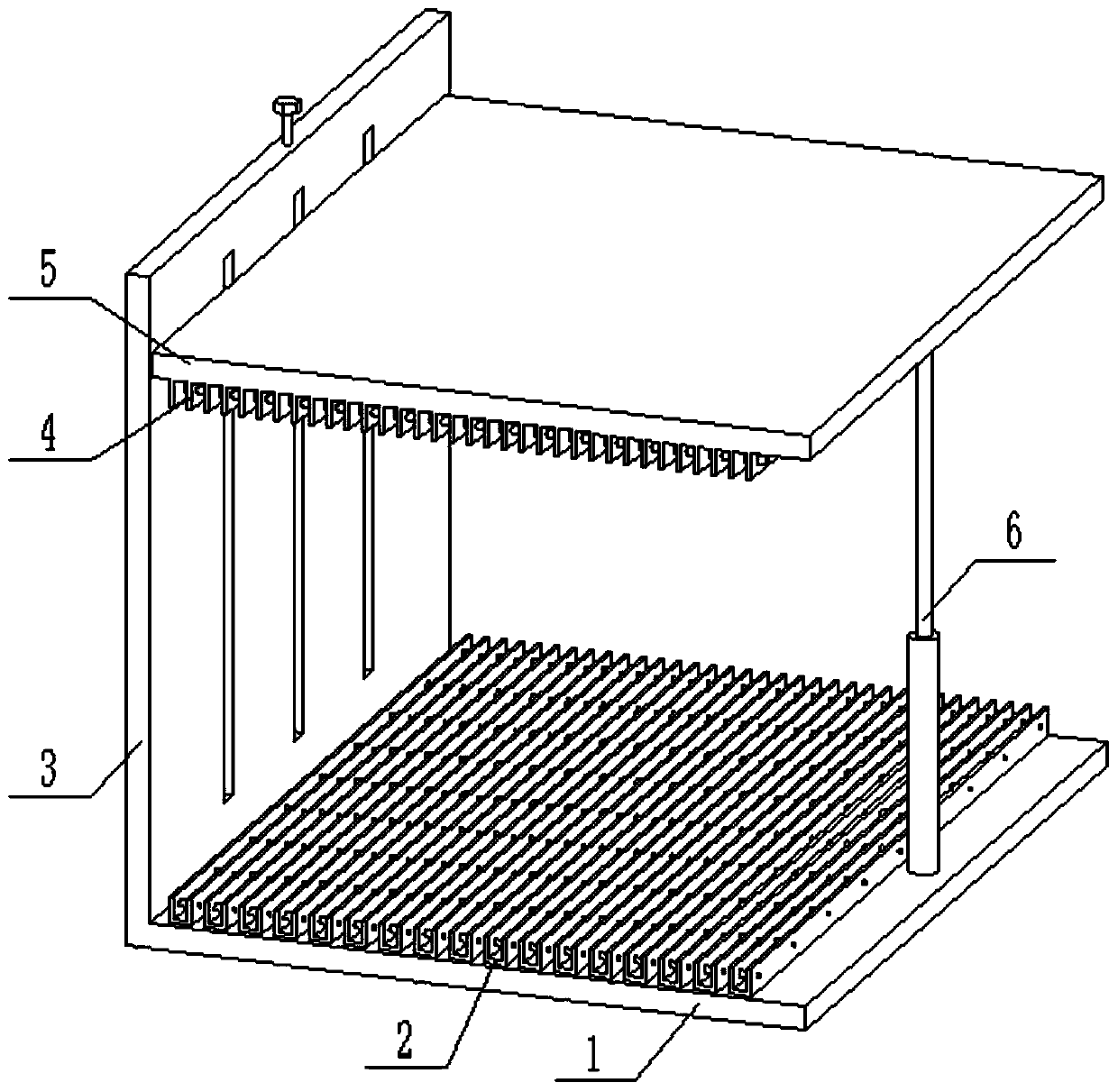
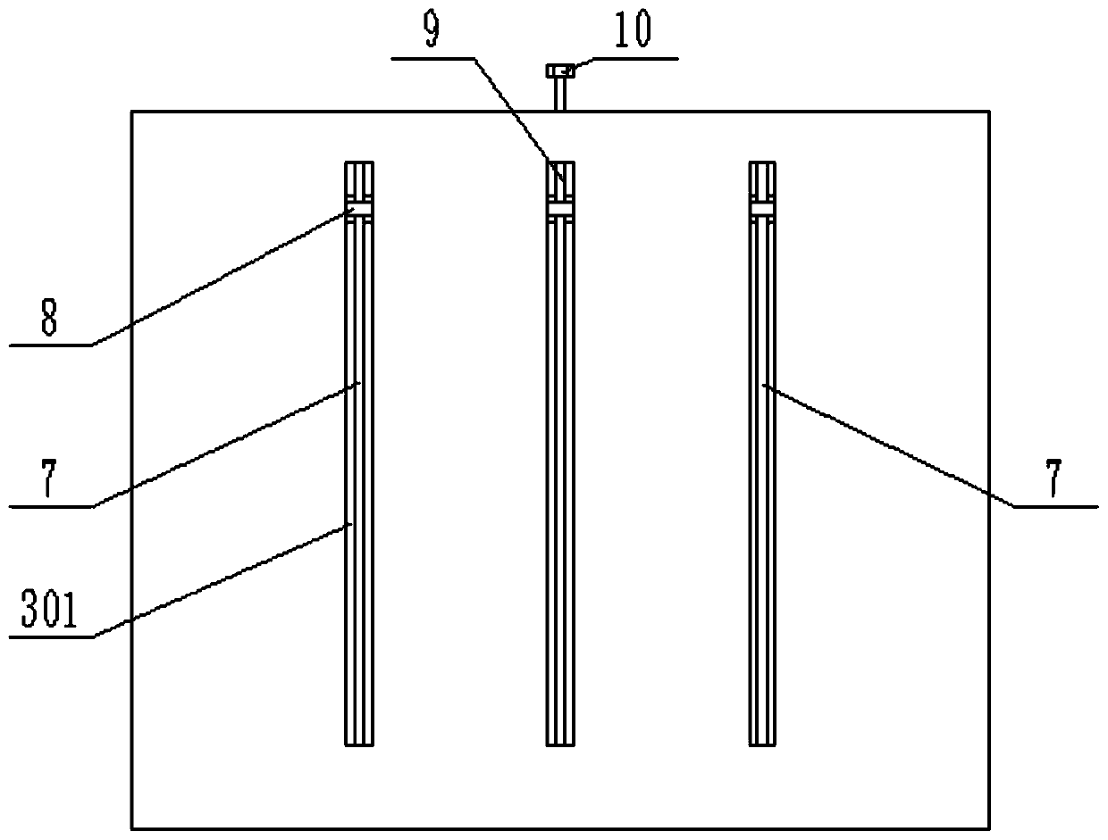
[0031] The first embodiment: see Figure 1-Figure 5 As shown, the present invention provides a shelf for glass transportation, including a fixed base plate 1, a support vertical plate 3 is installed on one side of the fixed base plate 1, and an adjustable support column 6 is installed on the other side of the fixed base plate 1, and the upper end of the fixed base plate 1 is uniform A guiding mechanism 2 is provided; three height-adjusting grooves 301 are provided through the surface of the supporting vertical plate 3, and a height-adjusting screw 9 is installed inside one of the height-adjusting grooves 301, and a guide shaft 7 is installed inside the other two height-adjusting grooves 301, and the guide shaft 7 is located on both sides of the height-adjusting screw 9; the lifting block 8 is installed on the height-adjusting screw 9 and the guide shaft 7, and the lifting plate 5 is installed on the end of the lifting block 8, and the lifting plate 5 is parallel to the fixed ba...

no. 2 approach

[0043] The second embodiment: a shelf for glass transportation, including a fixed bottom plate 1, characterized in that: a support vertical plate 3 is installed on one side of the fixed bottom plate 1, and an adjustable support column 6 is installed on the other side of the fixed bottom plate 1 , the upper end of the fixed bottom plate 1 is evenly provided with a guide mechanism 2; the surface of the support vertical plate 3 is provided with three height adjustment grooves 301, one of which is equipped with a height adjustment screw 9 inside the height adjustment groove 301, and the other two The guide shaft 7 is installed inside the height adjustment groove 301, and the guide shaft 7 is located at both sides of the height adjustment screw 9; the lift block 8 is installed on the height adjustment screw 9 and the guide shaft 7, wherein the height adjustment screw The front of the lifting block 8 on the bar 9 is provided with a threaded hole, the lifting block 8 on the guide shaf...


PUM


Abstract

The invention discloses a placing rack for glass transport. The placing rack comprises a fixed baseplate, wherein a supporting vertical plate is mounted on one side of the fixed baseplate; a guiding mechanism is arranged at the upper end of the fixed baseplate; three height adjusting grooves penetrate the surface of the supporting vertical plate; a height adjusting lead screw is mounted in one ofthe height adjusting grooves; guiding shafts are mounted in the other two height adjusting grooves; lifting blocks are mounted on the height adjusting lead screw and the guiding shafts; a lifting plate is mounted at the end parts of the lifting blocks; and a fixing mechanism is arranged at the bottom of the lifting plate. The placing rack has the following beneficial effects: glass can be separately placed through the guiding mechanism and the fixing mechanism, and therefore, is prevented from direct contact which leads to surface abrasion; a slide bar slides in a slide cavity by means of an elastic force of a compression spring, so that a compression block compresses the glass and the glass is fixed; and the height adjusting lead screw is rotated to enable the lifting blocks to drive thelifting plate to ascend and descend, so that the height of the lifting plate is adjusted, and the requirement for placing glass of different sizes is satisfied.

Description

technical field [0001] The invention relates to the technical field of auxiliary devices for glass production, in particular to a placing rack for glass transportation. Background technique [0002] Glass is a transparent, airtight, and hard material that is used in many fields. In the process of glass production and transportation, in order to protect the glass, the glass is often placed on a shelf for transportation of the glass. [0003] The applicant found that there are at least the following technical problems in the prior art: when placing the glass in the current rack, the direct contact between the glass and the glass is easy to cause the glass surface to be worn; Complicated, affecting the transportation efficiency of glass. Contents of the invention [0004] The object of the present invention is to provide a glass transportation shelf in order to solve the above problems, so as to solve the problem that the glass is in direct contact with the glass when the c...

Claims


Application Information

Patent Timeline
Patent Type & Authority Patents(China)
IPC IPC(8): B65G49/06
CPCB65G49/062
Inventor 于骏浩
Owner 于骏浩
Why Eureka
Try Eureka