
Friction forward and reverse rotation rotating shaft structure

A rotating shaft, positive and negative rotation technology, applied in the field of frictional positive and negative rotation shaft structure, can solve the problems of roughness, tightness and difficult adjustment, and achieve high viscoelasticity, good dimensional stability, and excellent chemical resistance.

Inactive Publication Date: 2018-10-12
DONGGUAN KTRUN LNTELLIGENT HOME FURNISHING CO LTD
View PDF6 Cites 0 Cited by
  • Summary
  • Abstract
  • Description
  • Claims
  • Application Information

AI Technical Summary

Problems solved by technology

However, the friction shaft in the existing shaft structure is relatively thick, and the tightness is not easy to adjust, which brings great inconvenience to the user, so it is necessary to adjust the shaft to improve these shortcomings

Method used


Image

  • Friction forward and reverse rotation rotating shaft structure
  • Friction forward and reverse rotation rotating shaft structure

Examples


Embodiment Construction

[0017] The technical solutions of the present invention will be clearly and completely described below in conjunction with the accompanying drawings. Apparently, the described embodiments are some of the embodiments of the present invention, but not all of them. Based on the embodiments of the present invention, all other embodiments obtained by persons of ordinary skill in the art without making creative efforts belong to the protection scope of the present invention.

[0018] In the description of the present invention, it should be noted that the terms "center", "upper", "lower", "left", "right", "vertical", "horizontal", "inner", "outer" etc. The indicated orientation or positional relationship is based on the orientation or positional relationship shown in the drawings, and is only for the convenience of describing the present invention and simplifying the description, rather than indicating or implying that the referred device or element must have a specific orientation, ...


PUM


Abstract

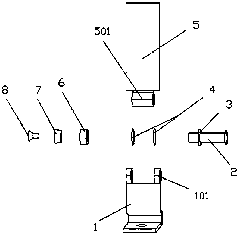
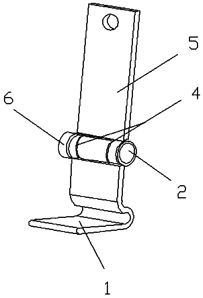
The invention discloses a friction forward and reverse rotation rotating shaft structure, and belongs to the technical field of rotating shaft devices. The structure comprises a movable rotating pieceA, a rotating shaft, a movable rotating piece B, a concave hinge shaft, a convex hinge shaft, a wear resisting gasket, a rotating shaft front positioning piece, a rotating shaft limiting wear-resistant bushing, a bearing upper fixed piece and a screw. The friction forward and reverse rotation rotating shaft structure has the following beneficial effects: the rotating shaft is additionally mountedin shaft holes of the concave hinge shaft and the convex hinge shaft, and a gap therebetween is contacted with the rotating shaft front positioning piece and the wear resisting gasket; the rotating shaft is locked and combined with the movable rotating piece A and the movable rotating piece B by the rotating shaft limiting wear-resistant bushing, the bearing upper fixed piece and the screw at theother end of the rotating shaft, so that the combination is locked, and the elasticity is easy to adjusted; the movable rotating piece A and the movable rotating piece B are enlarged, so that the proportional sizes of shafts and parts can be correspondingly increased; and the structure is suitable for any technical field needing the rotating shaft, high in adaptability and easy to popularize.

Description

technical field [0001] The invention relates to the technical field of a rotating shaft device, in particular to a frictional forward and reverse rotating shaft structure. Background technique [0002] The existing rotating shaft structure uses a screw and a shaft core to connect two or more working objects. The rotating shaft structure generates friction during the rotation process, and the rotating shaft structure can rotate and stop arbitrarily. However, the friction shaft in the existing rotating shaft structure is relatively thick, and the tightness is not easy to adjust, which brings great inconvenience to the user, so it is necessary to adjust the shaft to improve these shortcomings. Contents of the invention [0003] In order to comprehensively solve the above-mentioned problems, especially for the deficiencies in the prior art, the present invention provides a frictional forward and reverse rotating shaft structure which can comprehensively solve the above-mention...

Claims


Application Information

Patent Timeline
Patent Type & Authority Applications(China)
IPC IPC(8): F16C11/04
CPCF16C11/04
Inventor 吕信宏吕权晋彭文涛
Owner DONGGUAN KTRUN LNTELLIGENT HOME FURNISHING CO LTD
Learn More