An inlet and outlet tube box for evenly distributing the flow in the tube of a tube heat exchanger

A tubular heat exchanger, evenly distributed technology, applied in the direction of heat exchanger shell, heat exchange equipment, lighting and heating equipment, etc., to achieve the effect of increasing the flow area and strong applicability

Active Publication Date: 2019-10-11
XI AN JIAOTONG UNIV
View PDF8 Cites 0 Cited by
  • Summary
  • Abstract
  • Description
  • Claims
  • Application Information

AI Technical Summary

Problems solved by technology

[0007] Aiming at the problems existing in the prior art, the present invention provides an inlet and outlet tube box for evenly distributing the flow in the tubes of the tube heat exchanger, which can effectively eliminate the flow deviation phenomenon of the working fluid in the tubes in the tube bundle, thereby reducing the The adverse effect of uneven flow distribution on the overall heat transfer performance of the heat exchanger, and at the same time reduce the temperature difference caused by the flow deviation of fluids in different tubes

Method used


Image

  • An inlet and outlet tube box for evenly distributing the flow in the tube of a tube heat exchanger
  • An inlet and outlet tube box for evenly distributing the flow in the tube of a tube heat exchanger
  • An inlet and outlet tube box for evenly distributing the flow in the tube of a tube heat exchanger

Examples


Embodiment Construction

[0037] The present invention will be further described in detail below in conjunction with specific embodiments, which are explanations of the present invention rather than limitations.

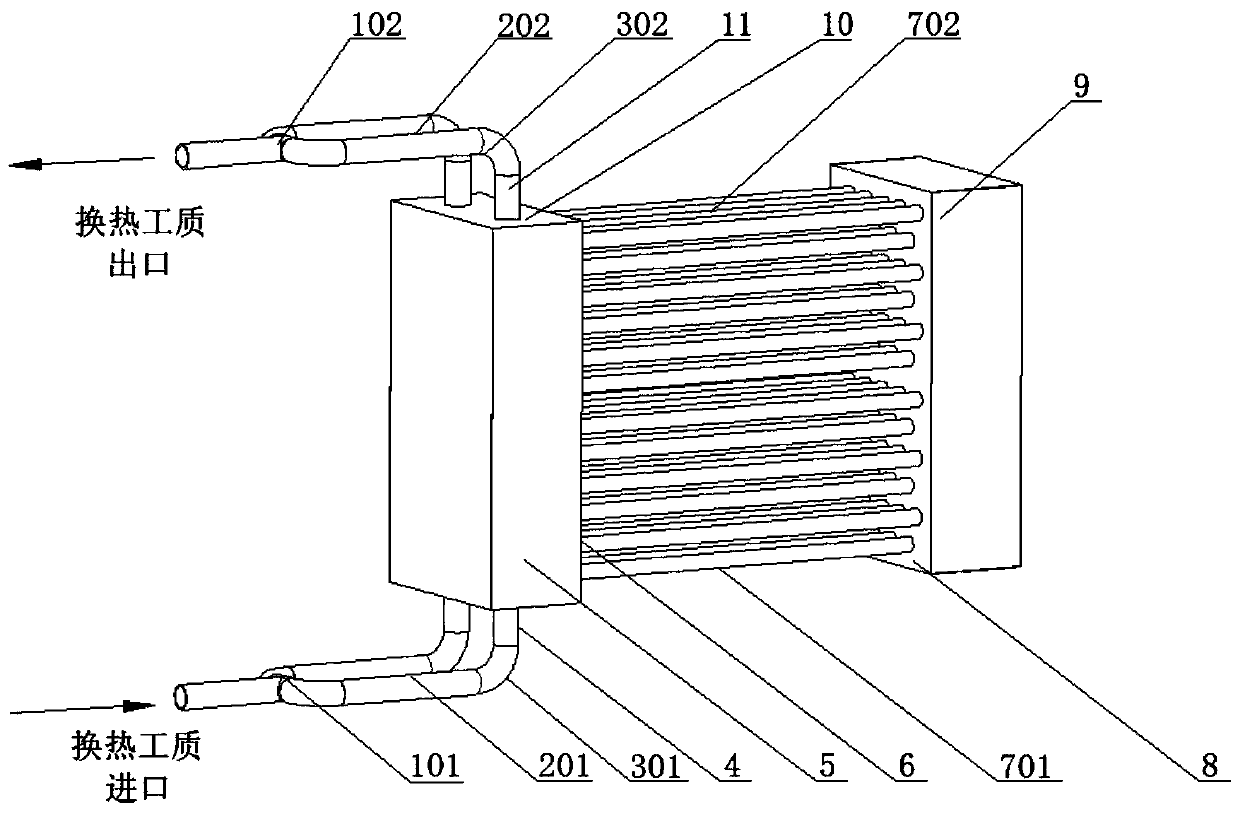
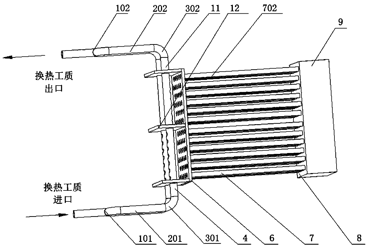
[0038] The invention is an inlet and outlet pipe box for evenly distributing the flow in the tube of a tubular heat exchanger, which can realize the uniform distribution of the flow of the heat exchange working medium in the heat exchange tube bundle, reduce the deviation of the flow in the tube, and reduce the flow caused by the flow of the working medium in the heat exchange tube. Uneven distribution has an adverse effect on the overall heat transfer efficiency of the heat exchanger. It is used in tube flue gas heat exchange devices in thermal power plants and related industrial processes, and can also be used for uniform distribution of working fluid flow in tube bundles of compact tube heat exchangers.

[0039] Such as figure 1 As shown, the present invention is an inlet and outlet tube ...


PUM


Abstract

The invention provides a uniform distribution tubular heat exchanger in-pipe flow inlet and outlet tube box structure. The tube bundle heat transferring uniform effectiveness can be effectively improved, and heat transfer disequilibrium caused by tube bundle non-uniform flow is reduced. The uniform distribution tubular heat exchanger in-pipe flow inlet and outlet tube box structure comprises an inlet tube box, tube bundles and an outlet tube box which are sequentially connected, comprises an inlet tee joint and even numbers of symmetrically-arranged inlet tubes which are connected with a heatexchange working medium inlet in sequence, and further comprises an outlet tee joint and even numbers of symmetrically-arranged outlet tubes which are connected with a heat exchange working medium outlet in sequence; the inlet tube box and the outlet tube box are separated through a middle separating plate and are connected with inlets and outlets of the tube bundles through a front end tube plate; an inlet tube extends into the inlet tube box, the side, back to the first tube pass tube bundle, of the inlet tube is provided with a plurality of incline holes punched in a downwards-inclined manner; and the outlet tube extends into the outlet tube box, and the side, facing the second tube pass tube bundle, of the outlet pipe is provided with a plurality of horizontally-punched flat holes.

Description

technical field [0001] The invention relates to tube bundle heat exchange equipment for tube heat exchange, in particular to an inlet and outlet tube box for evenly distributing flow in tubes of a tube heat exchanger. Background technique [0002] The flue gas generated by coal / gas fired boilers is accompanied by huge waste heat and contains SO x , NO x , HCl, HF and other acid gases, the direct discharge not only causes a large amount of heat loss, but also causes a series of environmental problems such as acid rain. Therefore, flue gas waste heat recovery and flue gas reheating devices are generally arranged on the tail flue of thermal power plant boilers or other industrial boilers. [0003] Flue gas waste heat recovery generally installs a flue gas cooler at the entrance of the wet flue gas desulfurization tower to reduce the flue gas temperature. After the flue gas passes through the flue gas cooler, the temperature can be reduced to below 90°C. On the one hand, the ...

Claims


Application Information

Patent Timeline
Patent Type & Authority Patents(China)
IPC IPC(8): F28F9/02F28F9/18
Inventor 赵钦新邵怀爽贾晓琳倪永涛梁志远王云刚
Owner XI AN JIAOTONG UNIV
Why Eureka
Try Eureka