Logic component correlation path generation method and system

A logic component and generation system technology, applied in the direction of creating/generating source code, visual/graphic programming, etc., can solve the problems of discounting experience effects and spending a lot of time on logic lines, and achieve the effect of improving efficiency and reducing storage

Inactive Publication Date: 2018-10-12
福州谛听科技有限公司
View PDF4 Cites 1 Cited by
  • Summary
  • Abstract
  • Description
  • Claims
  • Application Information

AI Technical Summary

Problems solved by technology

[0002] With the continuous development of society, in the field of industrial automation control, people have higher and higher requirements for experience. Engineers also begin to pay attention to experience effects in the process of writing logic. Part of the time, but this part of the time is doing r...

Method used


Image

  • Logic component correlation path generation method and system
  • Logic component correlation path generation method and system
  • Logic component correlation path generation method and system

Examples


Embodiment Construction

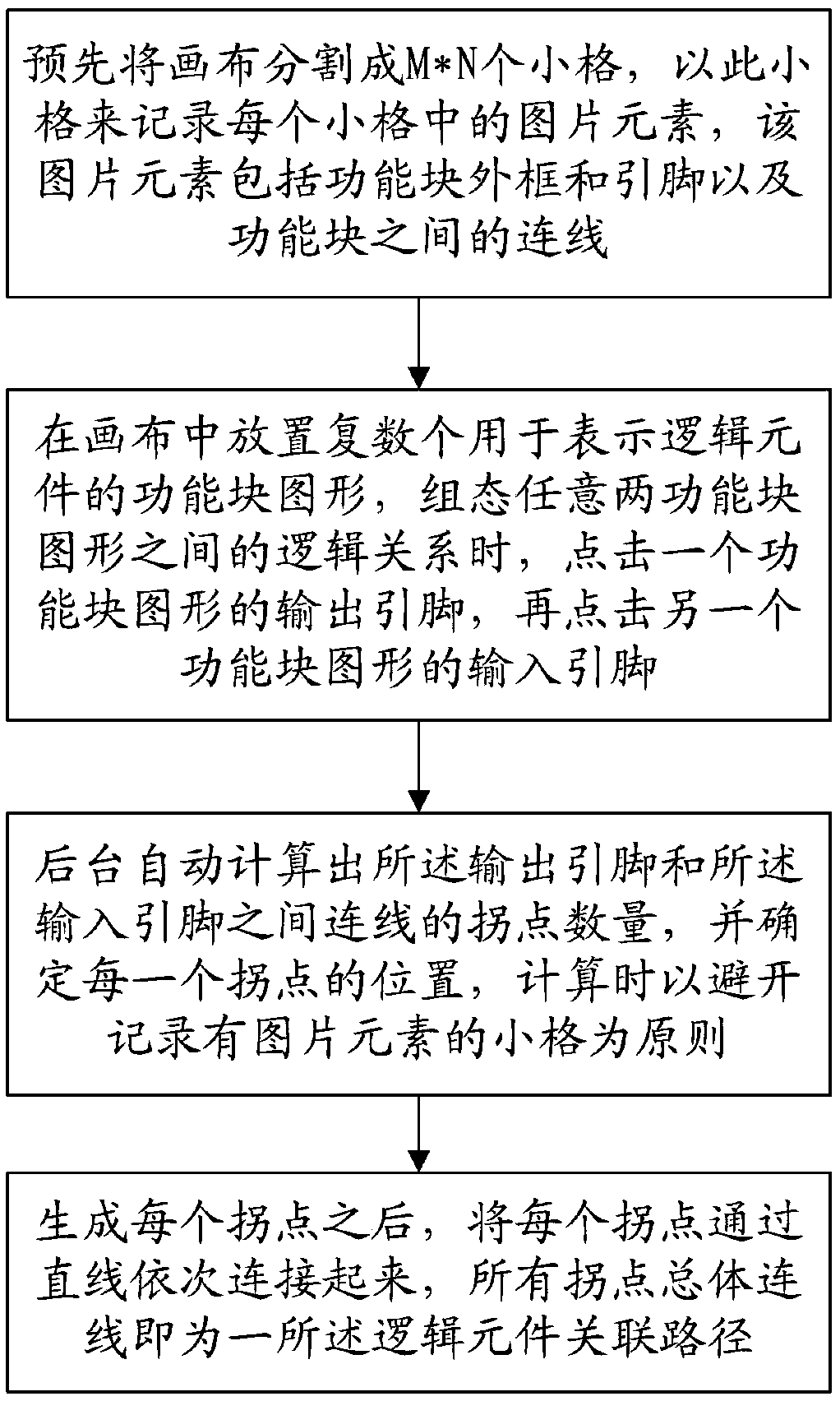
[0027] see Figure 1 to Figure 4 As shown, the generation method of the logic element association path of the present invention includes:

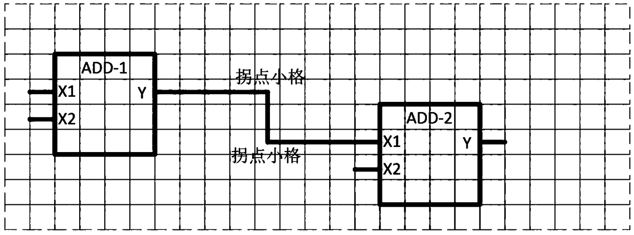
[0028] Step S1, such as figure 2 As shown, the canvas is divided into M*N small grids in advance, and the picture elements in each small grid are recorded in this small grid. The picture elements include the graphic information of the function block, the outer frame of the graphic, the position of the pin, and the type of the pin , pin descriptions and connections between functional blocks; in a specific embodiment, the M*N is 60*80.

[0029] Step S2, such as image 3 As shown, place a plurality of function block graphics representing logic components on the canvas, and when configuring the logical relationship between any two function block graphics, click the output pin of one function block graphic, and then click another function block graphic the input pin;

[0030] Step S3, the background automatically calculates and determines ...


PUM


Abstract

The invention provides a logic component correlation path generation method and system. The method comprises the steps of segmenting a canvas into M*N cells in advance, and recording picture elementsin the cells by the cells; placing multiple functional block graphs used for representing logic components in the canvas, and when a logic relationship between any two functional block graphs is configured, clicking an output pin of one functional block graph and clicking an input pin of the other functional block graph; automatically calculating out and judging a type relationship between the output pin and the input pin by a background, generating an inflection point quantity of a connection line, and determining the position of each inflection point cell; and after each inflection point cell generates an inflection point picture element, enabling the cell between the two adjacent inflection point cells to generate a straight line picture element, wherein the overall connection line of all the inflection point picture elements and the straight line picture elements is namely a logic component correlation path. Through the method and the system, an engineer only needs to specify starting and terminating ends of the path; and the optimal path is automatically generated through a path algorithm.

Description

technical field [0001] The invention relates to the field of industrial automation control, in particular to a method and system for generating associated paths of logic elements in the process of logic writing. Background technique [0002] With the continuous development of society, in the field of industrial automation control, people have higher and higher requirements for experience. Engineers also begin to pay attention to experience effects in the process of writing logic. Part of the time, but this part of the time is doing repetitive mechanical work, not part of the engineering relationship, and the experience effect is also greatly reduced. [0003] In the process of writing logic, engineers sometimes spend a lot of time in order to organize the logic lines between components, and cannot focus more on the relationship between the logic itself. Therefore, if the work of sorting out the logical lines between components can be automatically performed by the automatic...

Claims


Application Information

Patent Timeline
IPC IPC(8): G06F8/34
CPCG06F8/34
Inventor 王勇王龙南康孝顺张晓群
Owner 福州谛听科技有限公司
Why Eureka
Try Eureka