Automatic assembly device for coil bobbin

A technology of automatic assembly device and coil skeleton, which can be used in assembly machines, relays, metal processing, etc., and can solve the problems of increased labor costs and low processing efficiency.

Active Publication Date: 2018-10-12
WENZHOU JIAJIE ELECTRIC
View PDF5 Cites 8 Cited by
  • Summary
  • Abstract
  • Description
  • Claims
  • Application Information

AI Technical Summary

Problems solved by technology

Generally, the assembly of the above-mentioned bobbins, yokes and static contacts is done manually, which greatly increases the labor cost and the processing efficiency is relatively low.

Method used


Image

  • Automatic assembly device for coil bobbin
  • Automatic assembly device for coil bobbin
  • Automatic assembly device for coil bobbin

Examples


Embodiment Construction

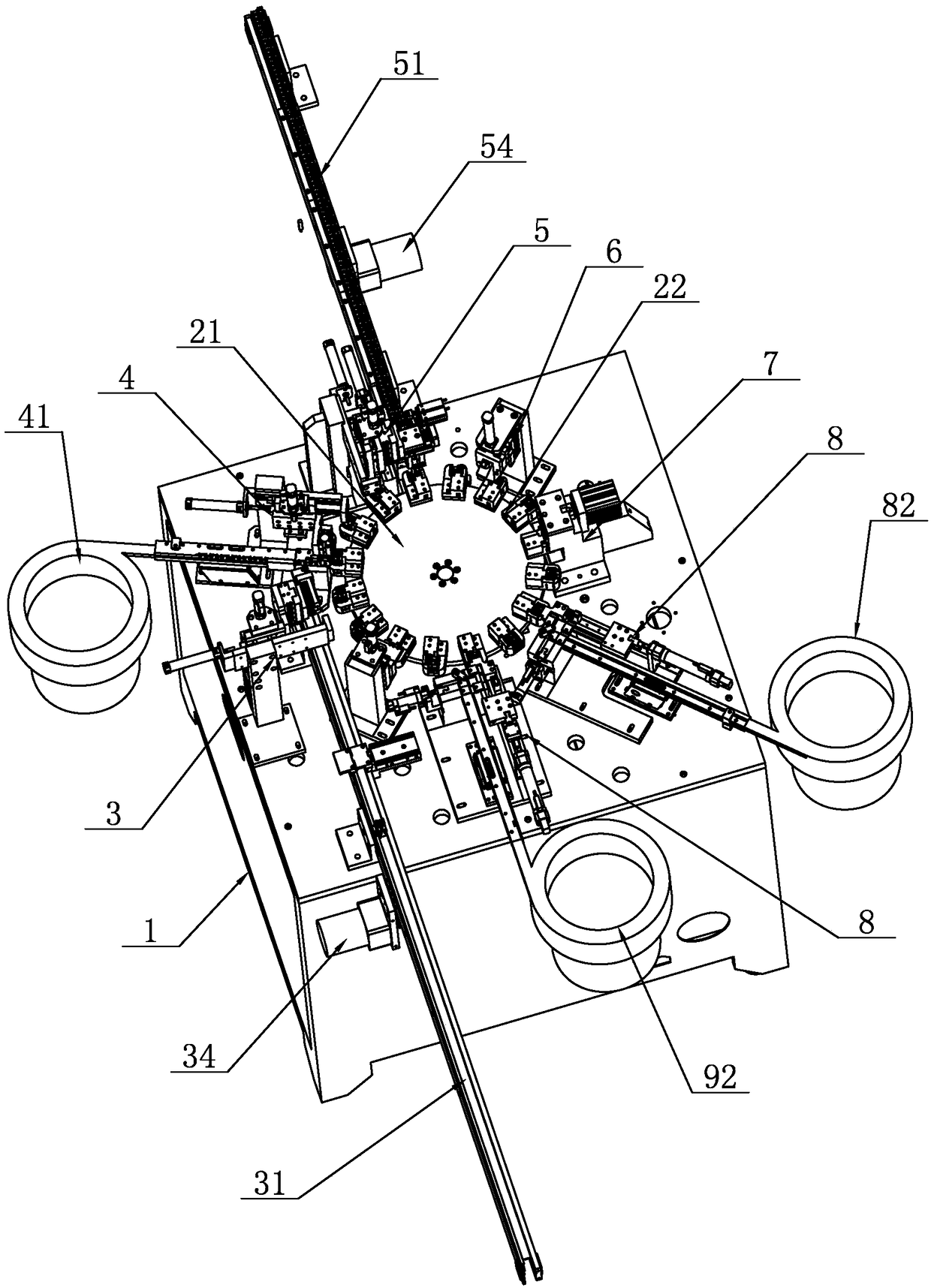
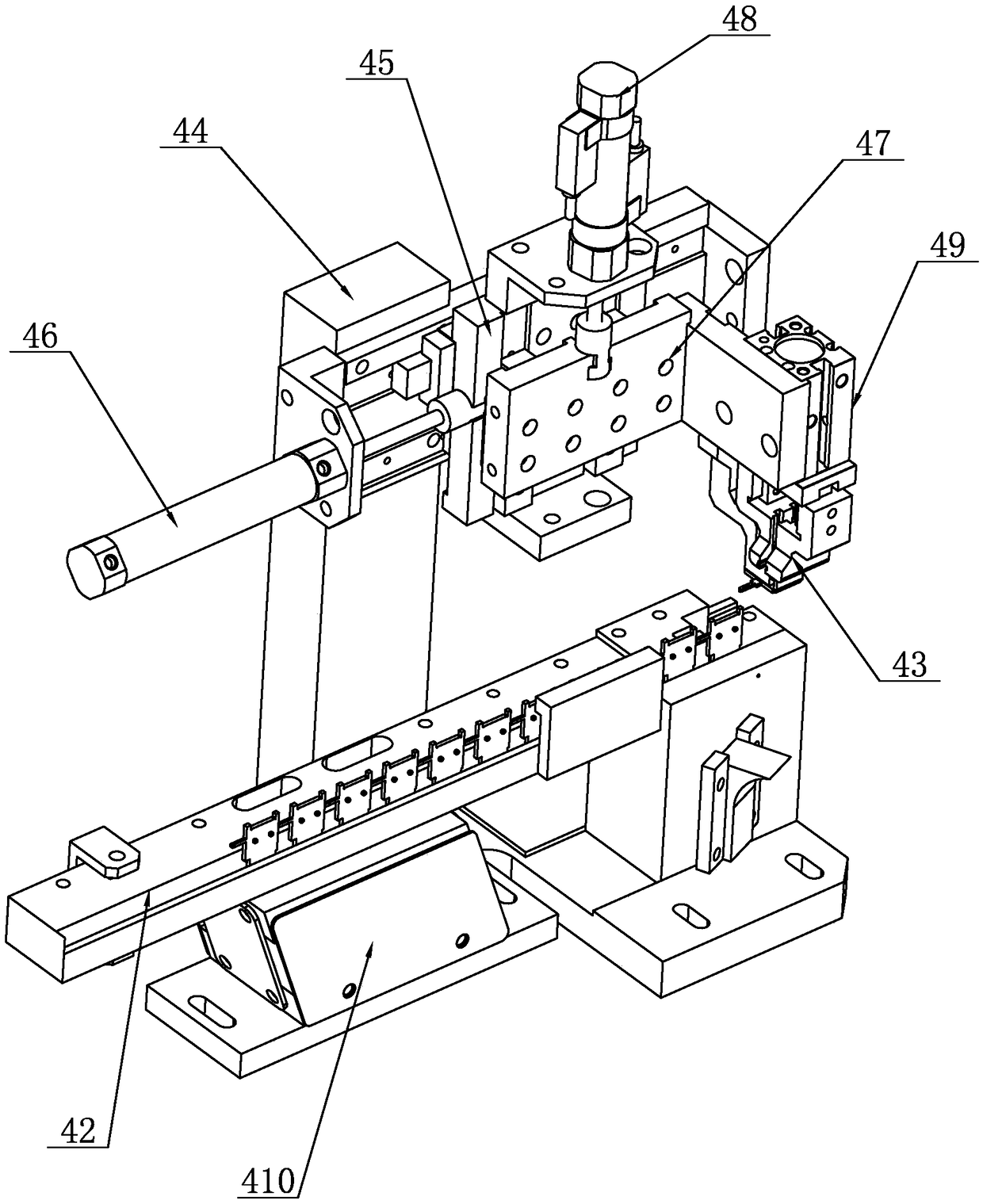
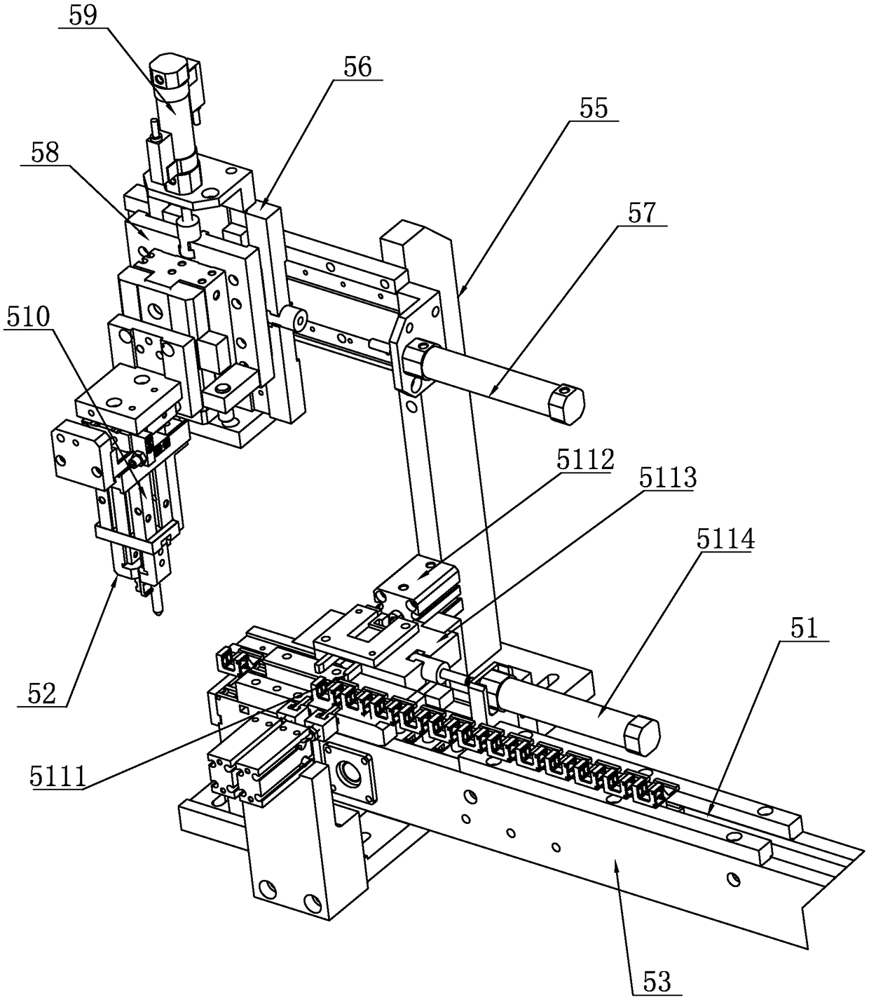
[0037] Such as Figure 1-Figure 12 As shown, an automatic assembly device for a coil bobbin includes a frame 1, on which a clamp mechanism 2, an assembly mechanism and a feeding mechanism 3 are arranged, the clamp mechanism 2 includes a turntable 21, and the turntable 21 is rotatably arranged on the frame 1 Above, the frame 1 is provided with a driving mechanism for driving the turntable 21 to rotate. The upper end surface of the turntable 21 is evenly distributed along its circumferential direction with several clip bodies 22 for placing the coil skeleton. The clip body 22 includes an upper clip body 221 and a lower clip body. 222, the lower clamping body 222 is fixedly arranged on the turntable 21, the upper clamping body 221 is fixedly arranged on the lower clamping body 222, and the accommodation groove 223 for the coil skeleton A1 is formed between the upper clamping body 221 and the lower clamping body 222, and the coil The skeleton A1 is placed on the accommodation groo...


PUM


Abstract

The invention relates to an automatic assembly device for a coil bobbin, comprising a frame, wherein the frame is provided with a clamp mechanism, an assembly mechanism and a cutting mechanism; the clamp mechanism comprises a turntable rotatably arranged on the frame, a driving mechanism for driving the turntable to rotate is arranged on the frame, the upper end surface of the turntable is uniformly distributed with a plurality of clips for the coil bobbin to be placed along the circumferential direction thereof, and the assembly mechanism includes a first assembly component for feeding the yokes to the clips, a second assembly component for feeding the bobbin to the clips, a third assembly component for feeding the nails to the clips, a fourth assembly component for riveting the nails, afifth assembly component for feeding the first static contact to the clips, and a sixth assembly component for feeding the second static contact to the clips. By adopting the above solution, the invention overcomes the deficiencies of the prior art, and provides an automatic assembly device for a coil bobbin, which is capable of realizing automatic assembly of the bobbin, yokes and static contactsin high processing efficiency.

Description

technical field [0001] The invention relates to the technical field of relay assembly, in particular to an automatic assembly device for a coil frame in a relay. Background technique [0002] The existing relay includes a coil frame, a yoke and a static contact piece, and the yoke iron and the static contact piece are all installed on the coil frame, such as figure 1 As shown, the coil bobbin A1 is wound with a coil, the yoke A2 is arranged in an L shape, and the yoke A2 is half surrounded and inserted on the coil bobbin A1, and the coil bobbin A1 is provided with a socket for the insertion of the nail A3 A11, the lower end of the yoke A2 is riveted to the lower part of the coil bobbin A1 through the iron nail A3, and the upper part of the coil bobbin A1 is provided with a first slot A12 and a second slot A13, and the first slot A12 is located in the second slot Below the slot A13 , the static contact piece includes a first static contact piece A4 inserted in the first slot...

Claims


Application Information

Patent Timeline
Patent Type & Authority Applications(China)
IPC IPC(8): H01H49/00B23P21/00B23P19/00
CPCB23P19/001B23P19/007B23P21/006H01H49/00
Inventor 虞乐克吴微克
Owner WENZHOU JIAJIE ELECTRIC
Why Eureka
Try Eureka