A method for preparing a terahertz lens antenna group

A technology of terahertz lens and lens antenna, which is applied in the field of terahertz wave imaging antenna, can solve the problems of difficulty in meeting requirements, increased cost, and inapplicability of large field of view, and achieve uniform beams and reduce processing difficulty.

Active Publication Date: 2020-08-04
NAT SPACE SCI CENT CAS
View PDF4 Cites 0 Cited by
  • Summary
  • Abstract
  • Description
  • Claims
  • Application Information

AI Technical Summary

Problems solved by technology

[0004] At present, the traditional preparation method of terahertz lens antenna adopts the preparation method of millimeter-wave lens antenna, such as the equal optical path method, but due to the equal optical path method, the optical path of the vertical incident beam and the edge incident beam can only be equal to obtain the optical path of the lens antenna. The expression, the lens antenna obtained by this preparation method has poor imaging effect when used in imaging systems, and is not suitable for large field of view
In order to achieve the uniformity of multi-beam gain, the traditional design method will use iterative algorithm, the accuracy of this method is significantly higher than the former, the designed lens antenna often uses a single lens with free-form surface, but the processing accuracy of the single-lens with free-form surface is quite demanding. High, difficult to meet the requirements, resulting in increased costs

Method used


Image

  • A method for preparing a terahertz lens antenna group
  • A method for preparing a terahertz lens antenna group
  • A method for preparing a terahertz lens antenna group

Examples


Embodiment Construction

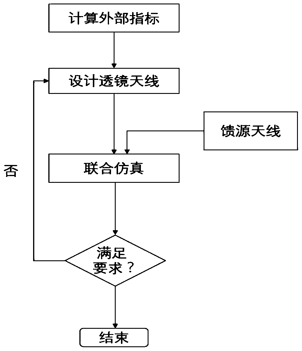
[0030] The present invention will be further described in detail below in conjunction with the accompanying drawings.

[0031] It is now further explained in conjunction with the accompanying drawings: to design a terahertz wave imaging dielectric lens antenna, the working object distance of the lens antenna is required to be 0.5m, the working frequency is 220GHz, and the resolution on the object plane is less than 15mm. According to the requirements of this index, the following is given A preparation method of a terahertz wave high-resolution imaging dielectric lens antenna group.

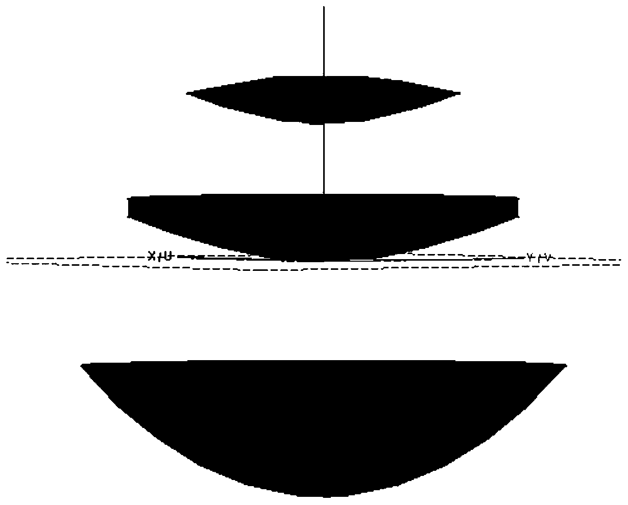
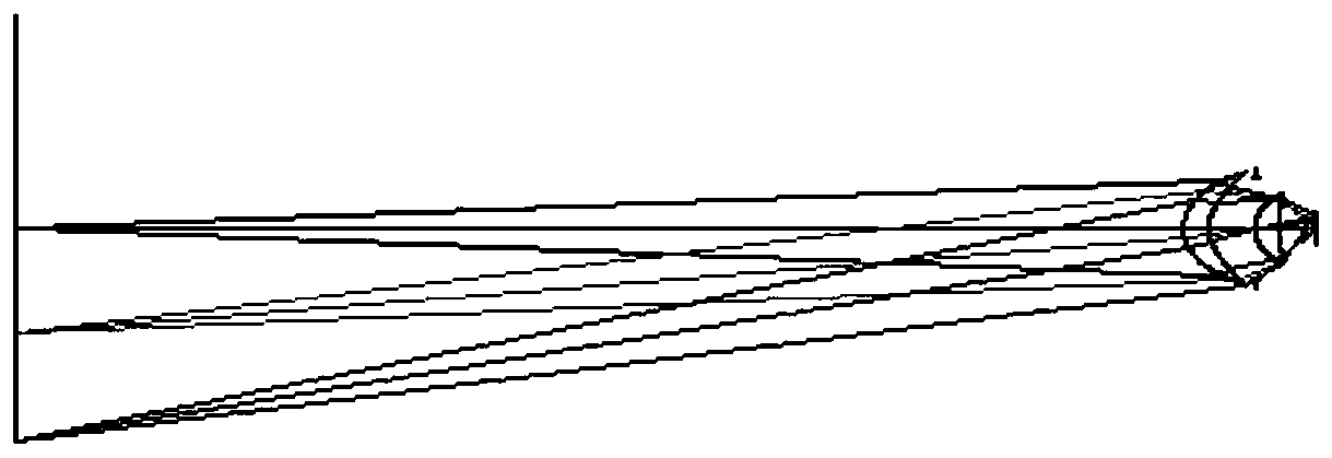
[0032] The main work of preparing the lens antenna group is the selection and optimization of the lens surface equation. The equivalent object distance of the lens antenna group is S 1 , the equivalent image distance of the lens antenna group is S 2 , the dielectric constant of the lens material is ε, and the equivalent diameter of the lens antenna group is D.

[0033] Both surfaces of the lens...


PUM


Abstract

The present invention provides a method for preparing a terahertz lens antenna group. The method comprises: step 1) calculating an unknown external index of the lens antenna group; and step 2) placingthe imaging target point on the object plane of a lens, and obtaining an optimized lens antenna by using the size of the light spot of the image plane of a quadric surface single lens; step 3) continuing to increase the number of quadric single lenses, and continuing to optimize the added quadric surface single lens, to obtain the optimized lens antenna group; step 4) for the lens antenna group obtained in the step 3), performing the tolerance analysis on the lens antenna group by adopting the Monte Carlo method, if the diameter of the light spot at the edge of the image plane is 10 times orlarger than the diameter of the light spot at the center point of the image plane, and the beam uniformity is greater than 3dB, repeating the steps 1) to 3); and step 5) placing the known feed antennaon the image plane by using the electromagnetic simulation software FEKO, to determine whether the diameter of the light spot focused on the object plane and multi-beam gain difference meet the requirement of the regulations.

Description

technical field [0001] The invention relates to the technical field of terahertz wave imaging antennas, in particular to a method for preparing a terahertz lens antenna group. Background technique [0002] The principle of terahertz passive imaging is similar to the principle of optical imaging. Due to the different working frequency bands, there must be differences in hardware design. This difference is mainly manifested in the form of the receiving part of the imaging system. The research of optical imaging has a history of more than 100 years, and the technology of this part has been mature and widely used in practice. However, the penetration of visible light and near-infrared systems is not good. In bad weather, dust, and dark days, the imaging effect is significantly worse. When the imaging object has thick packaging, visible light and even near-infrared light waves are difficult to penetrate. Therefore, the terahertz wave whose frequency is significantly lower than t...

Claims


Application Information

Patent Timeline
Patent Type & Authority Patents(China)
IPC IPC(8): H01Q19/06H01Q15/02
CPCH01Q15/02H01Q19/06
Inventor 刘喆张德海
Owner NAT SPACE SCI CENT CAS
Why Eureka
Try Eureka