Non-orthogonal multiple access method based on massive mimo

A technology of non-orthogonal multiple access and access method, which is applied in the field of non-orthogonal multiple access based on massive MIMO, and can solve the limitations of the orthogonal multiple access scheme, many time-frequency resources, lack of solutions, etc. question

Active Publication Date: 2020-09-08
BEIJING JIAOTONG UNIV
View PDF2 Cites 0 Cited by
  • Summary
  • Abstract
  • Description
  • Claims
  • Application Information

AI Technical Summary

Problems solved by technology

[0003] Disadvantages of Orthogonal Multiple Access Technology: In the context of massive wireless devices in future networks, especially the Internet of Things, the limitations of traditional Orthogonal Multiple Access solutions are gradually emerging
[0005] Disadvantages of non-orthogonal multiple access technology based on spreading code domain: For this non-orthogonal multiple access scheme based on spreading code domain, the time-frequency resources required by a specific transmission block (Transmission Block, TB) will be It is several times the time-frequency resources required in traditional orthogonal multiple access, so more time-frequency resources are occupied. It can be said that it is a method of exchanging more time-frequency resources for transmission efficiency
[0007] Disadvantages of non-orthogonal multiple access technology (NOMA) based on the power domain: a major challenge for 5G mobile communications in the future is the surge in the number of connections in the uplink direction, while the traditional NOMA mainly studies the transmission problem in the downlink direction, and concentrates on Multiplexing in a single power domain, so how to use NOMA to solve the concurrent access of a large number of uplink terminals is an unsolved problem
However, there is still a lack of relevant solutions for how to make NOMA technology suitable for massive MIMO scenarios to obtain higher user access.

Method used


Image

  • Non-orthogonal multiple access method based on massive mimo
  • Non-orthogonal multiple access method based on massive mimo
  • Non-orthogonal multiple access method based on massive mimo

Examples


Embodiment Construction

[0097] The following is attached Figure 1-4 The present invention is described in further detail.

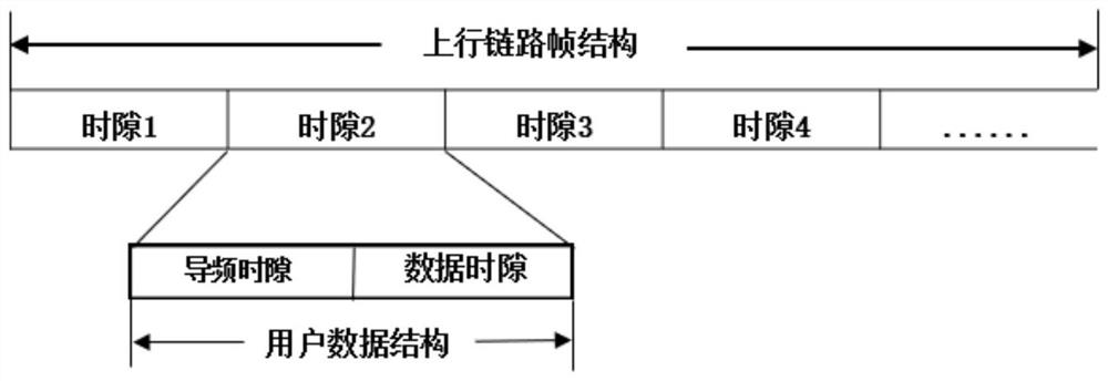
[0098] 1. System model:

[0099]The present invention considers a wireless communication scenario using massive MIMO technology. Assuming that the base station is equipped with M antennas, the index of the antenna is represented by m, and m=1,2,...,M. In the cell served by the base station, K single-antenna users share a certain pilot sequence and transmit their respective uplink data. The index of the user is represented by k, and k=1,2,...,K. The uplink transmit power of user k is p k , which indicates the transmit power used for pilot or data transmission, depending on the situation. The uplink channel gain corresponding to user k is denoted as where β k is the path loss coefficient, h k is the small-scale fading channel of user k. h k =[h k,1 , h k,2 ,...,h k,M ] T Contains M independent and identically distributed components, [.] T Represents the transpose o...


PUM


Abstract

The present invention relates to a non-orthogonal multiple access method based on massive MIMO, comprising the following steps: step 1: determine the optimal demodulation sequence, step 2: determine the receiving power of the user, and step 3: determine the optimal demodulation sequence of the user Transmit power, step 4: determine the data frame structure: different users accessing the same base station follow the same uplink frame structure to send synchronously, and the length of the time slot used by the user does not exceed the coherence time of the wireless channel; step 5: pilot selection Method: The way for users to obtain pilots is that each user independently randomly selects the pilots they use from a given set of pilots; Step 6: On the basis of Steps 4 and 5, multiple user terminals transmit The power sends signals to the base station. After receiving the signal, the base station uses the channel hardening capability of massive MIMO to estimate the composite channel of multiple users only at the antenna end, and uses the serial interference cancellation technology to finally complete the recovery of all user signals.

Description

technical field [0001] The invention relates to the technical fields of wireless communication, massive MIMO system and multiple access, and in particular to a non-orthogonal multiple access method based on massive MIMO. Background technique [0002] Orthogonal Multiple Access Technology: Traditional communication systems are based on Orthogonal Multiple Access (OMA) technology. These technologies first divide wireless resources, and then allocate one or more Orthogonal resources in a domain are allocated to different users. Among them, the orthogonality of resources determines the orthogonality between user signals, so that multiple users can complete data transmission without interfering with each other, thereby simplifying the design of the base station receiver. [0003] Disadvantages of Orthogonal Multiple Access Technology: In the context of massive wireless devices in future networks, especially the Internet of Things, the limitations of traditional Orthogonal Multip...

Claims


Application Information

Patent Timeline
Patent Type & Authority Patents(China)
IPC IPC(8): H04B7/0452H04B7/0426H04L25/02H04L25/03
CPCH04B7/0426H04B7/0452H04L25/03159H04L25/0204Y02D30/70
Inventor 刘铭刘念王庆
Owner BEIJING JIAOTONG UNIV
Why Eureka
Try Eureka