Laying type training device for arm power

A training device and arm strength technology, which is applied to heavy objects, sports accessories, gymnastics equipment, etc., can solve the problem of single function of fitness equipment, and achieve the effects of wide applicability, convenient use and improved service life.

Inactive Publication Date: 2018-10-16
安徽上造智能设备科技有限公司
8 Cites 0 Cited by

AI-Extracted Technical Summary

Problems solved by technology

[0003] The purpose of the present invention is to provide a lying arm strength training device. By providing a lying board and pillars and movable columns on both sides of the lying board, and a weight-lifting device is installed on the mov...

Method used

[0033] Wherein, the handle portion of the lifting rod 5 is provided with an anti-skid rubber cover, and ...

Abstract

The invention discloses a laying type training device for arm power, and relates to the technical field of fitness equipment. The horizontal type training device comprises a bottom plate, a laying plate is fixed to the upper surface of the bottom plate through multiple supporting pillars, braces are symmetrically arranged on the portions, on the upper surface of the bottom plate, of the two sidesof the laying plate, and a movable pillar is fixed to one end of each brace; a weightlifting device is installed on and matched with the two movable pillars, and comprises a weightlifting rod, ring bodies are arranged at the two ends of the weightlifting rod respectively, linear bearings movably matched with the movable pillars are arranged inside the ring bodies, an elastic buffering structure isarranged on the bottom side face of each ring body, a weight fixing shaft is further fixed to one side of each ring body, and multiple weights are installed on the weight fixing shafts. By arrangingthe laying plate, arranging the braces and the movable pillars on the two sides of the laying plate, and installing the weightlifting device on the movable pillars through matching, waist and leg power is exercised while people lie on the laying plate to have arm power exercise, and the problem is solved that the functions of an existing fitness instrument are monotonous.

Application Domain

Weights

Technology Topic

Exercise equipmentEngineering

Image

  • Laying type training device for arm power
  • Laying type training device for arm power
  • Laying type training device for arm power

Examples

  • Experimental program(1)

Example Embodiment

[0027] The technical solutions in the embodiments of the present invention will be clearly and completely described below in conjunction with the accompanying drawings in the embodiments of the present invention. Obviously, the described embodiments are only a part of the embodiments of the present invention, rather than all the embodiments. Based on the embodiments of the present invention, all other embodiments obtained by those of ordinary skill in the art without creative work shall fall within the protection scope of the present invention.
[0028] In the description of the present invention, it should be understood that the terms “upper” and “end” indicate the orientation or positional relationship, only for the convenience of describing the present invention and simplifying the description, rather than indicating or implying that the referred components or elements must It has a specific orientation and is constructed and operated in a specific orientation, so it cannot be understood as a limitation to the present invention.
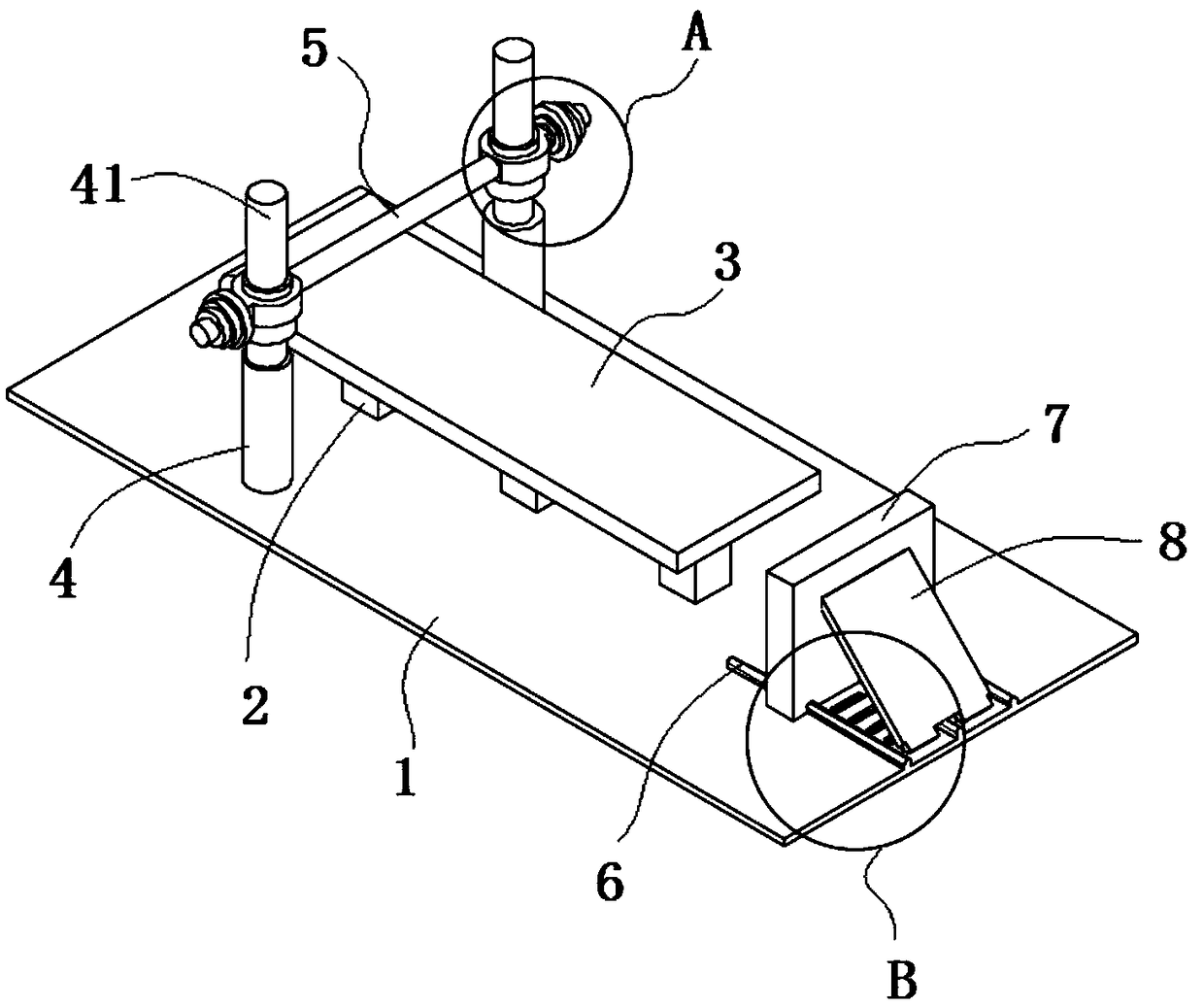
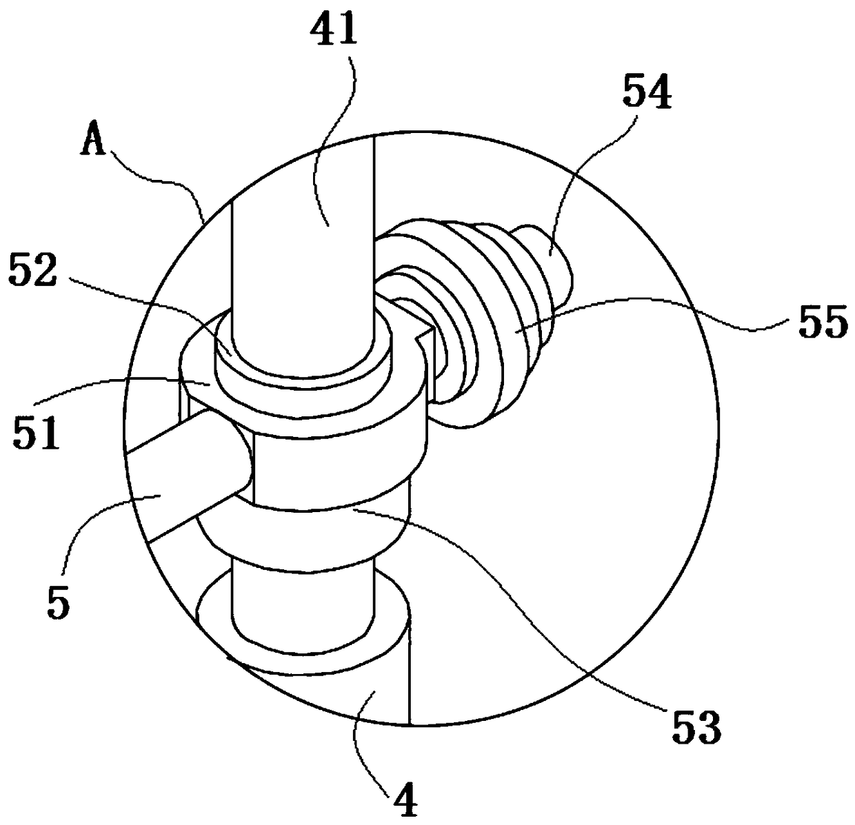
[0029] See Figure 1-3 As shown, the present invention is a lying-down arm strength training device, which includes a bottom plate 1. A lying plate 3 is fixed on the upper surface of the bottom plate 1 through a plurality of support columns 2, and the upper surface of the bottom plate 1 on both sides of the lying plate 3 is symmetrically provided with pillars 4, A movable column 41 is fixed at one end of the pillar 4; two movable pillars 41 are fitted with a weightlifting device. The weightlifting device includes a lifting rod 5. Both ends of the lifting rod 5 are provided with a ring body 51. The linear bearing 52 is movably matched with the column 41. An elastic buffer structure 53 is provided on the bottom side of the ring body 51. A weight fixing shaft 54 ​​is also fixed on one side of the ring body 51. A number of weights are mounted on the weight fixing shaft 54 55;
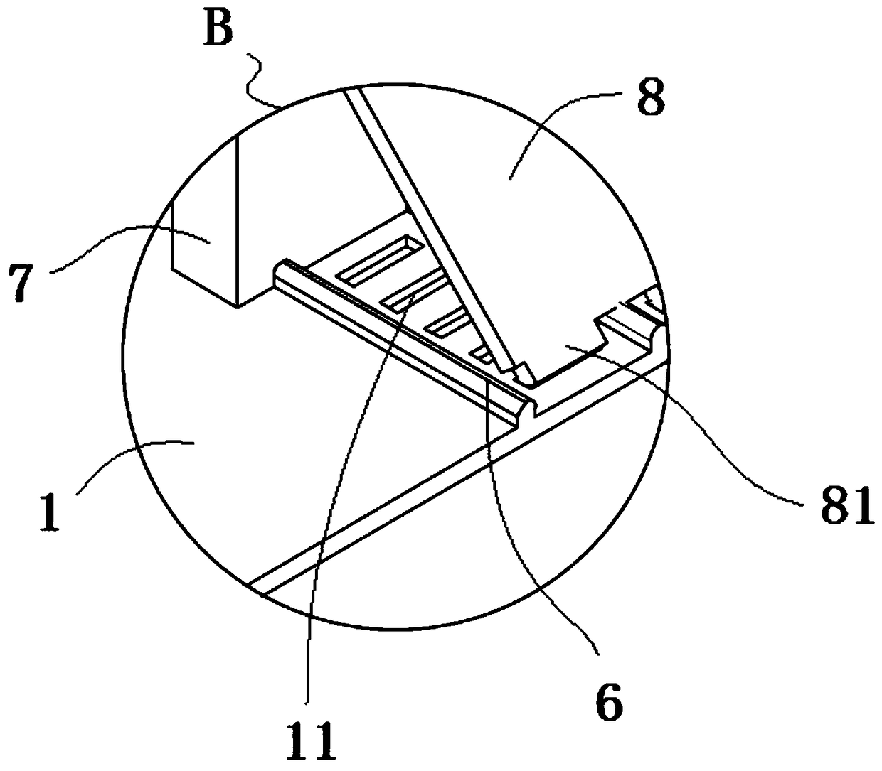
[0030] A number of guide rails 6 are provided on the upper surface of the bottom plate 1 at one end of the lying board 3, and a pedal 7 is slidably fitted on the plurality of guide rails 6; a number of limit recesses are evenly distributed on the upper surface of the bottom plate 1 between the two guide rails 6 along the sliding direction of the guide rails 6 Slot 11, one surface of the pedal 7 is hingedly fitted with a support plate 8; one end of the support plate 8 is hingedly fitted to the pedal 7, and the other end of the support plate 8 is provided with a number of limit cards that cooperate with the limit grooves 11 牙81.
[0031] Wherein, a pillow cushion is provided on one end of the lying board 3, which is convenient for lying on the lying board 3 with pillow cushions to support the neck and head positions.
[0032] Among them, the diameter of the movable column 41 is 1-2 cm smaller than the diameter of the pillar 4, and the guide action of the movable pillar 41 causes the weightlifting device to move up and down along the movable pillar 41. Due to the size difference between the movable pillar 41 and the pillar 4, the movable pillar 41 passes through the pillar 4 The lifting height of the weight lifting device is restricted to prevent the weight lifting device from moving down too much and compressing the body.
[0033] Among them, a non-slip rubber sleeve is sheathed on the handle of the lifting rod 5, and the weight lifting device is moved by holding the anti-slip rubber sleeve to effectively prevent slipping.
[0034] Among them, the elastic buffer structure 53 is a rubber washer with a thickness of 1-2cm. The rubber washer can effectively reduce the damage to the pillar 4 during the downward movement of the weightlifting device, improve the service life of the device, and reduce noise generation, which is beneficial to creation A good fitness environment.
[0035] Among them, the end surface of the guide rail 6 is an isosceles trapezoid or dovetail structure, and the bottom side of the pedal 7 is provided with an isosceles trapezoid or dovetail structure notch that matches with the guide rail 6; through the design of the isosceles trapezoid or dovetail structure, It is convenient for the pedal 7 to slide along the guide rail 6, and at the same time, through the supporting effect of the support plate 8, it is convenient for the pedal 7 to support.
[0036] Among them, the two pillars 4 are located at the shoulder positions on both sides of the lying board 3.
[0037] Among them, the two sides of the lying board 3 are also provided with handrails.
[0038] Among them, when in use, lie on the lying board 3, with the feet against the pedal 7; head on the pillow, hold the non-slip rubber sleeve on the lifting rod 5 and move the weight lifting device up and down along the movable column 41 to exercise arm strength Function.
[0039] In the description of this specification, the description with reference to the terms "one embodiment", "example", "specific example", etc. means that the specific feature, structure, material or characteristic described in combination with the embodiment or example is included in at least the present invention. In one embodiment or example. In this specification, the schematic representations of the above terms do not necessarily refer to the same embodiment or example. Moreover, the described specific features, structures, materials or characteristics may be combined in any one or more embodiments or examples in a suitable manner.
[0040] The preferred embodiments of the present invention disclosed above are only used to help explain the present invention. The preferred embodiment does not describe all the details in detail, nor does it limit the invention to only the described specific embodiments. Obviously, many modifications and changes can be made according to the content of this manual. This specification selects and specifically describes these embodiments in order to better explain the principles and practical applications of the present invention, so that those skilled in the art can understand and use the present invention well. The present invention is only limited by the claims and their full scope and equivalents.

PUM

PropertyMeasurementUnit
Thickness1.0 ~ 2.0cm

Description & Claims & Application Information

We can also present the details of the Description, Claims and Application information to help users get a comprehensive understanding of the technical details of the patent, such as background art, summary of invention, brief description of drawings, description of embodiments, and other original content. On the other hand, users can also determine the specific scope of protection of the technology through the list of claims; as well as understand the changes in the life cycle of the technology with the presentation of the patent timeline. Login to view more.

Similar technology patents

Glomerocryst cubic boron nitride composite sheet and preparation method for same

ActiveCN103158287AExtended service lifeIncreased depth of cut
Owner:ZHENGZHOU BERLT HARD MATERIALS

Sleep assistance mattress

ActiveCN106842979AReduce data processing pressureExtended service life
Owner:DONGGUAN UNIV OF TECH

Recovering and using technology of water in electroplating

Owner:海宁市海整整流器有限公司

Classification and recommendation of technical efficacy words

  • Extended service life
  • reduce noise

Fracturing manifold quick connecting device

Owner:YANTAI JEREH PETROLEUM EQUIP & TECH

Modified asphalt composition with creeping characteristic and preparation method thereof

InactiveCN102020859Aavoid rapid agingExtended service life
Owner:ZHEJIANG WOPUMAN HIGH NEW MATERIALS

Noise reduction device

ActiveUS20100014683A1reduce noisehigh quality
Owner:PANASONIC CORP

Digital camera with underwater capture mode

InactiveUS20110228075A1reduce noise
Owner:INTELLECTUAL VENTURES FUND 83 LLC
Why Eureka
Try Eureka