Ceiling splicing structure and splicing method thereof

A technology for suspended ceilings and splicing panels, applied in the direction of ceilings, building components, building structures, etc., can solve problems such as affecting the aesthetics of the ceiling structure, affecting the structure of the concrete layer, and prone to cracks, and achieving good splicing effect, improving effect and improving quality. Effect

Inactive Publication Date: 2018-10-16
DONGGUAN UNIV OF TECH
View PDF0 Cites 1 Cited by
  • Summary
  • Abstract
  • Description
  • Claims
  • Application Information

AI Technical Summary

Problems solved by technology

[0002] In the process of house decoration, most of the ceilings will be suspended. Most of the existing ceilings are four-sided ceilings, which are made of plates. Because the structure of the house is large, most of them will use the ceiling splicing structure. The splicing structure is two ceiling panels. The connection structure of the existing ceiling boards is mostly connected by wooden pins to join the two boards together, there will be a certain gap, and cracks will easily appear after a period of painting, which will affect the beauty of the entire ceiling structure. For this In this case, a certain degree of change has been made in the splicing structure, that is, after the sides of the two boards are spliced ​​by wooden pins, a groove is dug on the lower surface of the two boards, steel wire mesh is placed in the groove, and then the concrete layer is filled. Ensure that there are no gaps on the lower surface of the splicing of the two boards, which can have a certain effect of preventing cracks after painting. This method can only ensure that there are no gaps on the lower surface of the splicing of the two boards, and there are still gaps in other parts. That is, there are gaps in the supporting layer of the concrete layer. After a long time, it will also affect the structure of the concrete layer and cause the wall paint to crack.

Method used


Image

  • Ceiling splicing structure and splicing method thereof
  • Ceiling splicing structure and splicing method thereof
  • Ceiling splicing structure and splicing method thereof

Examples


Embodiment 1

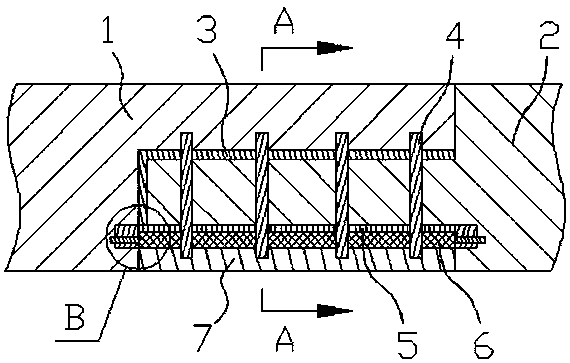
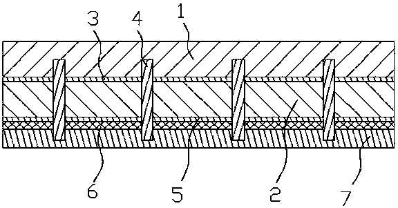
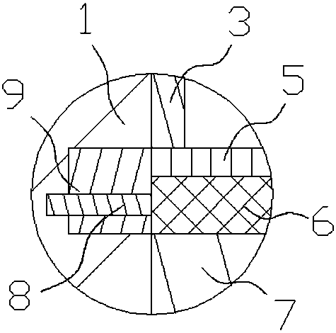
[0026] ①. First, the first splicing block and the second splicing block are cut and formed from the first splicing plate and the second splicing plate respectively by cutting equipment, and then the first splicing block and the second splicing block are assembled and spliced ​​from the bottom to the top hole, and then open a square matching groove on the sides of the first splicing plate and the second splicing plate, and then use the punching equipment to open a wire mesh fixing bolt matching pin hole in the square matching hole;

[0027] ②. Put the first splicing plate processed in step ① upside down, and then apply adhesive glue on the lower surface of the first splicing block and the side of the first splicing plate, and then insert the wire mesh fixing pin of the steel mesh into the second splicing plate. The wire mesh fixing pins in the splicing plate fit into the pin holes, and then put the end of the second splicing block on the first splicing block, and then push the f...

Embodiment 2

[0031] ①. First, the first splicing block and the second splicing block are cut and formed from the first splicing plate and the second splicing plate respectively by cutting equipment, and then the first splicing block and the second splicing block are assembled and spliced ​​from the bottom to the top hole, and then open a square matching groove on the sides of the first splicing plate and the second splicing plate, and then use the punching equipment to open a wire mesh fixing bolt matching pin hole in the square matching hole;

[0032] ②. Put the first splicing plate processed in step ① upside down, and then apply adhesive glue on the lower surface of the first splicing block and the side of the first splicing plate, and then insert the wire mesh fixing pin of the steel mesh into the second splicing plate. The wire mesh fixing pins in the splicing plate fit into the pin holes, and then put the end of the second splicing block on the first splicing block, and then push the f...

Embodiment 3

[0036] ①. First, the first splicing block and the second splicing block are cut and formed from the first splicing plate and the second splicing plate respectively by cutting equipment, and then the first splicing block and the second splicing block are assembled and spliced ​​from the bottom to the top hole, and then open a square matching groove on the sides of the first splicing plate and the second splicing plate, and then use the punching equipment to open a wire mesh fixing bolt matching pin hole in the square matching hole;

[0037]②. Put the first splicing plate processed in step ① upside down, and then apply adhesive glue on the lower surface of the first splicing block and the side of the first splicing plate, and then insert the wire mesh fixing pin of the steel mesh into the second splicing plate. The wire mesh fixing pins in the splicing plate fit into the pin holes, and then put the end of the second splicing block on the first splicing block, and then push the fi...


PUM


Abstract

The invention relates to a ceiling splicing structure and a splicing method thereof. A first splicing block flush with the upper surface of a first splicing plate is arranged on the side face of the first splicing plate, a second splicing block is arranged in the middle of the side face of a second splicing plate, and the first splicing plate and the second splicing plate are connected through vertical splicing wood pins. The distance between the upper side of the second splicing block and the upper surface of the second splicing plate is consistent with the thickness of the first splicing block, a bonding glue layer is arranged on the contact positions of the first splicing plate and the first splicing block with the second splicing block, and a steel wire net is arranged on the lower surface of the second splicing block. The side face of the steel wire net penetrates into the first splicing plate and the second splicing plate through wire net fixing bolts, and the lower portion of the steel wire net is integrally connected with a concrete layer flush with the lower surfaces of the first splicing plate and the second splicing plate. Through improvement on the structure and splicing mode of the two splicing plates, it can be ensured that the supporting face of the upper portion of the concrete layer is a seamless plane, it is ensured that the structure of the concrete layer isstable for a long time, and the function of wall paint cracking prevention of the ceiling splicing structure is achieved.

Description

technical field [0001] The invention relates to the field of plate structures, in particular to a ceiling splicing structure and a splicing method thereof. Background technique [0002] In the process of house decoration, most of the ceilings will be suspended. Most of the existing ceilings are four-sided ceilings, which are made of plates. Due to the large structure of the house, most of them will use the ceiling splicing structure. The splicing structure is two ceiling panels. The connection structure of the existing ceiling boards is mostly spliced ​​together by wooden pins, and there will be a certain gap. After a period of painting, cracks are prone to appear, which affects the appearance of the entire ceiling structure. For this In this case, a certain degree of change has been made in the splicing structure, that is, after splicing the sides of the two boards with wooden pins, a groove is dug on the lower surface of the splicing of the two boards, steel wire mesh is p...

Claims


Application Information

Patent Timeline
Patent Type & Authority Applications(China)
IPC IPC(8): E04B9/04E04B1/68
CPCE04B9/0435E04B1/68E04B1/6801
Inventor 邓君刘晓蔚
Owner DONGGUAN UNIV OF TECH
Why Eureka
Try Eureka